Gateway ECU Power Source Circuit
Circuit diagnosis
DESCRIPTION
This is the power source circuit to operate the gateway ECU.WIRING DIAGRAM
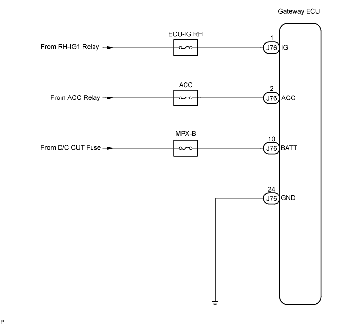

INSPECTION PROCEDURE
| 1. INSPECT GATEWAY ECU |

Disconnect the gateway ECU connector J76.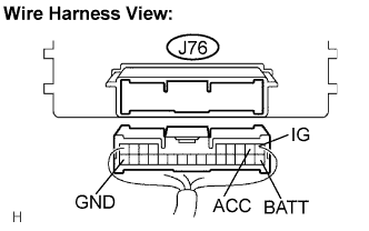
Measure the resistance according to the value(s) in the table below.
- Standard resistance:
Tester connection
Condition
Specified condition
GND - Body ground
Always
Below 1 Ω
Measure the voltage according to the value(s) in the table below.
- Standard voltage:
Tester connection
Condition
Specified condition
BATT - GND
Always
10 to 14 V
ACC - GND
Engine switch on (ACC)
10 to 14 V
IG - GND
Engine switch on (IG)
10 to 14 V
|
|
||||

| OK | ||
 |
||
| ||