DIAGNOSIS DISPLAY DETAILED DESCRIPTION
Troubleshooting
- HINT:
- This section contains a detailed description of displays within diagnostic mode.
- Illustrations may differ from the actual vehicle depending on the device settings and options. Therefore, some detailed areas may not be shown exactly the same as on the actual vehicle.
- This section contains a detailed description of displays within diagnostic mode.
| SYSTEM CHECK |
System Check Mode Screen
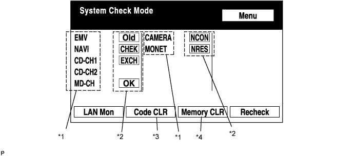

Device Names and Hardware Address/*1
- HINT:
- Registered device names are displayed.
- If a device name is unknown to the system, its physical address is shown instead.
- Registered device names are displayed.
Address No.
Name
Address No.
Name
110
EMV
120
AVX
128
1DIN TV
140
AVN
144
G-BOOK
178
NAVI
17C
MONET
190
AUDIO H/U
1AC
CAMERA-C
1B0
Rr-TV
1C0
Rr-CONT
19D
BT-HF
1C4
PANEL
1C6
G/W
1C8
FM-M-LCD
1D8
CONT-SW
1EC
Body
118
EMVN
1F1
XM
1F2
SIRIUS
230
TV-TUNER
240
CD-CH2
250
DVD-CH
280
CAMERA
360
CD-CH1
3A0
MD-CH
17D
TEL
440
DSP-AMP
530
ETC
1F6
RSE
1A0
DVD-P
1D6
CLOCK
238
DTV
480
AMP
Check Result/*2
- HINT:
- Result codes for all devices are displayed.
Result
Meaning
Action
OK
The device did not respond with a DTC (excluding communication DTCs from the AVC-LAN).
-
EXCH
The device responds with a "replace"-type DTC.
Look up the DTC in "Unit Check Mode" and replace the device.
CHEK
The device responds with a "check"-type DTC.
Look up the DTC in "Unit Check Mode".
NCON
The device was previously present, but does not respond in diagnostic mode.
- Check power supply wire harness of the device.
- Check the AVC-LAN of the device.
Old
The device responds with an "old"-type DTC.
Look up the DTC in "Unit Check Mode".
NRES
The device responds in diagnostic mode, but gives no DTC information.
- Check power supply wire harness of the device.
- Check the AVC-LAN of the device.
- Check power supply wire harness of the device.
Code Clear/*3
- Present DTCs are cleared.
- Press the "Code CLR" switch for 3 seconds.
- Present DTCs are cleared.
Memory Clear/*4
- Present and past DTCs and registered connected device names are cleared.
- Press the "Memory CLR" switch for 3 seconds.
- Present and past DTCs and registered connected device names are cleared.
Diagnosis MENU Screen
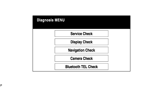
- HINT:
- Each item is grayed out or not displayed based on the device settings.
Unit Check Mode Screen
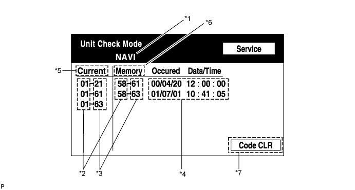
Screen Description: Display
Contents
Device name/*1
Target device
Segment/*2
Target device logical address
DTC/*3
DTC (Diagnostic Trouble Code)
Timestamp/*4
The time and date of past DTCs are displayed. (The year is displayed in 2-digit format.)
Present Code/*5
DTCs output at the service check are displayed.
Past Code/*6
Diagnostic memory results and recorded DTCs are displayed.
Diagnosis Clear Switch/*7
Pushing this switch for 3 seconds clears the diagnostic memory data of the target device. (Both response to diagnostic system check result and the displayed data are cleared.)
LAN Monitor (Original) Screen
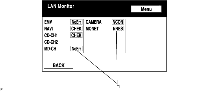
Check Result/*1
- HINT:
- Check results of all the devices are displayed.
Result
Meaning
Action
No Err (OK)
There are no communication DTCs.
-
CHEK
The device responds with a "check" -type DTC.
Look up the DTC in "Unit Check Mode".
NCON
The device was previously present, but does not respond in diagnostic mode.
- Check power supply wire harness of the device.
- Check the AVC-LAN of the device.
Old
The device responded with an "old" -type DTC.
Look up the DTC in "Unit Check Mode".
NRES
The device responds in diagnostic mode, but gives no DTC information.
- Check power supply wire harness of the device.
- Check the AVC-LAN of the device.
- Check power supply wire harness of the device.
LAN Monitor (Individual) Screen
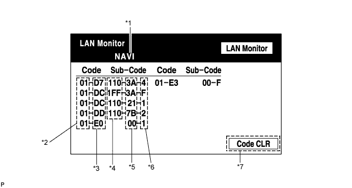
Screen Description: Display
Contents
Device name/*1
Target device
Segment/*2
Target logical address
DTC/*3
DTC (Diagnostic Trouble Code)
Sub-code (device address)/*4
Physical address stored with DTC (If there is no address, nothing is displayed.)
Connection check No./*5
Connection check number stored with DTC
DTC occurrence/*6
Number of times the same DTC has been recorded
Diagnosis Clear Switch/*7
Pushing this switch for 3 seconds clears the diagnostic memory data of the target device. (Both response to diagnostic system check result and the displayed data are cleared.)
| DISPLAY CHECK |
Vehicle Signal Check Mode Screen
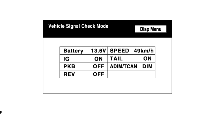
Screen Description: Name
Contents
Battery
Battery voltage is displayed.
PKB
Parking brake ON/OFF state is displayed.
REV
Reverse signal ON/OFF state is displayed.
IG
Engine switch ON/OFF state is displayed.
ADIM/TCAN
Brightness state DIM (with) / BRIGHT (without) is displayed.
TAIL
TAIL signal (Light control switch) ON/OFF state is displayed.
SPEED
Vehicle speed is displayed in km/h.
- HINT:
- Only items sending a vehicle signal will be displayed.
- This screen is updated once per second when input signals to the vehicle are changed.
- Only items sending a vehicle signal will be displayed.
Microphone & Voice Recognition Check Screen
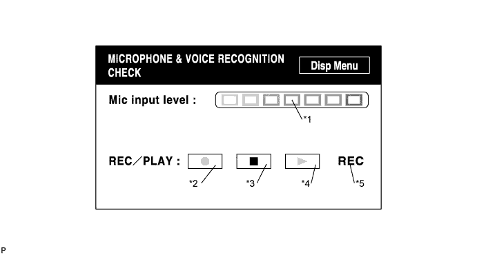
Screen Description: Name
Contents
Microphone input level meter/*1
Monitors the microphone input level every 100 ms and displays the results in 8 different levels.
Recording switch/*2
Starts recording.
Stop switch/*3
Stops recording.
Play switch/*4
Plays the recorded voice.
Recording indicator/*5
Comes on while recording.
- HINT:
- The microphone input function is on at all times when this screen is displayed.
- While recording or playing, the switches other than the stop switch cannot be pushed.
- When no voice is recorded, the play switch cannot be pushed.
- Recording will stop after 5 seconds or by pushing the stop switch.
- The microphone input function is on at all times when this screen is displayed.
CAN Connection Check Screen
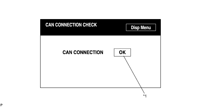
Screen Description: Name
Contents
CAN Connection check result/*1
- For systems connected to the CAN system, the results of the CAN connection check are displayed.
- "NG" - The engine switch is on (ACC or IG) and the CAN communication lines are malfunctioning or the CAN bus lines are not connected.
- "OK" - The engine switch is on (ACC or IG) and the CAN communication lines are normal.
- Blank - CAN connection check is performed with the engine switch is on (ACC) or off.
- HINT:
- This function operates only for the systems connected to the CAN system.
- When the engine switch is turned off, the bus lines are disconnected, or a malfunction occurs in the bus lines while the CAN connection check result is being displayed, the problem will be reflected on the screen in real time.
- This function operates only for the systems connected to the CAN system.
- For systems connected to the CAN system, the results of the CAN connection check are displayed.
| NAVIGATION CHECK |
Navigation Check Screen
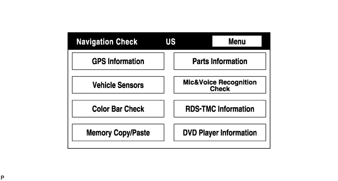
- HINT:
- Each item is grayed out or not displayed based on the device settings.
GPS Information Screen
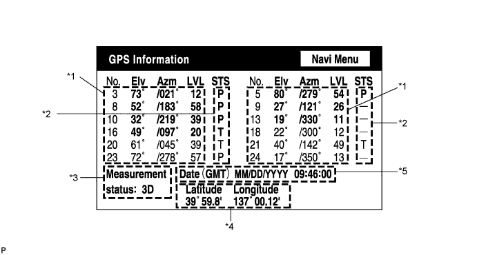
Satellite information/*1
Information from a maximum of 12 satellites is displayed on the screen. This information includes the target GPS satellite number, elevation angle, direction, and signal level.Receiving condition/*2
(DENSO model): Display
Contents
T
The system is receiving a GPS signal, but is not using it for location.
P
The system is using the GPS signal for location.
-
The system cannot receive a GPS signal.
(AISIN AW model): Display
Contents
01H
The system cannot receive a GPS signal.
02H
The system is tracing a satellite.
03H
The system is receiving a GPS signal, but is not using it for location.
04H
The system is using the GPS signal for location.
Measurement information/*3: Display
Contents
2D
2-dimensional location method is being used.
3D
3-dimensional location method is being used.
NG
Location data cannot be used.
Error
Reception error has occurred.
-
Any other state.
Position information/*4 Display
Contents
Position
Latitude and longitude information on the current position is displayed.
Date information/*5: Display
Contents
Date
The date/time information obtained from GPS signal is displayed in Greenwich mean time (GMT). The last 4 digits are displayed.
Vehicle Sensors Screen
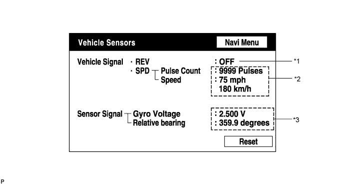
Vehicle signal: Display
Contents
REV/*1
REV signal ON/OFF state is displayed.
SPD/*2
SPD signal condition is displayed.
Sensor signal: Display
Contents
Gyro sensor/*3
Gyro sensor output condition is displayed (when the vehicle runs straight or is stationary, the voltage is approximately 2.5 V).
- HINT:
- Signals are updated once per second only when vehicle sensor signals are changed.
Microphone & Voice Recognition Check Screen
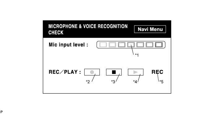
Screen Description: Display
Contents
Microphone input level meter/*1
Monitors the microphone input level every 100 ms and displays the results in 8 different levels.
Recording switch/*2
Starts recording.
Stop switch/*3
Starts recording.
Play switch/*4
Plays the recorded voice.
Recording indicator/*5
Comes on while recording.
- HINT:
- The microphone input function is on at all times when this screen is displayed.
- While recording or playing, the switches other than the stop switch cannot be pushed.
- When no voice is recorded, the play switch cannot be pushed.
- Recording will stop after 5 seconds or by pushing the stop switch.
- The microphone input function is on at all times when this screen is displayed.
RDS-TMC Information Screen (Only Europe)
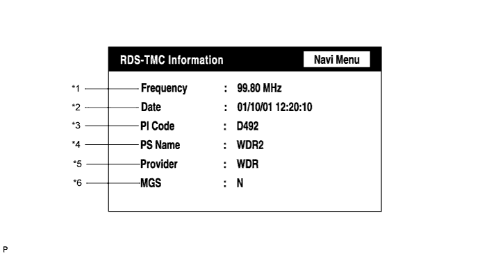
Frequency/*1 Display
Contents
Frequency
The latest received frequency, at which an RDS-TMC signal is detected, is displayed.
Date of update/*2 Display
Contents
Date
The latest date and time of TMC signal detection are displayed. (Greenwich mean time)
PI code/*3 Display
Contents
PI code
Broadcast station identification code (to identify the content of the program) is displayed.
PS name/*4 Display
Contents
PS name
Broadcast station name is displayed.
Provider name/*5 Display
Contents
Provider
The name of the TMC provider (TMC information source) is displayed (max. 8 characters).
MGS/*6 Display
Contents
MGS
The latest radio reception area is displayed.
The letter "N", "R", and/or "U" is displayed depending on the reception area.
- HINT:
- If radio wave has never been received, "-" is displayed for all the items.
- As for the MGS, "N" shows a domestic level, "R" shows a local level, and "U" shows a city level. If 2 or 3 levels are applicable, the letters are displayed in a line.
- RDS-TMC information is not updated in DTC mode.
- If radio wave has never been received, "-" is displayed for all the items.
DVD Played Information Screen
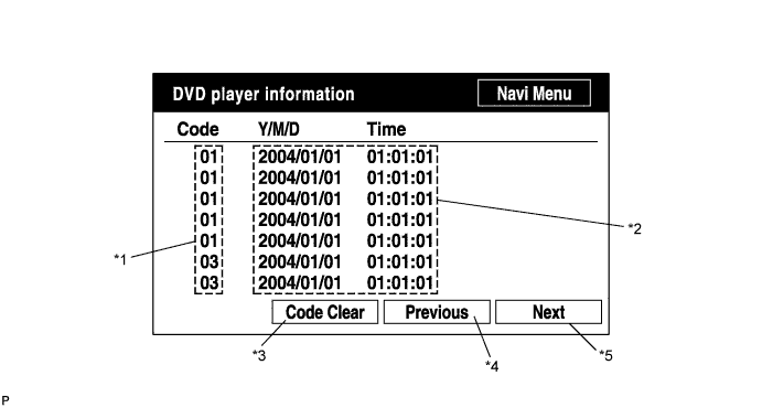
Screen Description: Display
Contents
Trouble code/*1
Each code corresponding to the malfunctions is displayed. For details, refer to "Trouble Code Description".
Occurrence time/*2
- The date (year, month, day) and time (hour, minute, second) when the trouble code was detected are displayed as a time stamp. (Greenwich mean time)
- The time data to be displayed are received from the GPS receiver.
Trouble code clear switch/*3
All code data being displayed are cleared by pushing this switch for 3 seconds.
Returning switch/*4
The previous page is displayed. If the current displayed page is the first page, this switch cannot be operated.
Proceeding switch/*5
The next page is displayed. If the current displayed page is the last page, this switch cannot be operated.
Trouble Code Description: Code
Malfunction
Countermeasure
01
Cannot be recognized
Replace navigation ECU.
03
Cannot be read
Follow the inspection procedure for DTC 58-42 (Click here).
- HINT:
- This is a DVD player check function in the navigation ECU.
- The date (year, month, day) and time (hour, minute, second) when the trouble code was detected are displayed as a time stamp. (Greenwich mean time)