REMOVAL
Removal / installation
| 1. DISCONNECT CABLE FROM NEGATIVE BATTERY TERMINAL |
| 2. REMOVE SHIFT LEVER KNOB SUB-ASSEMBLY |

Turn the shift lever knob counterclockwise and remove the shift lever knob sub-assembly.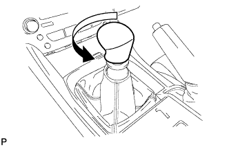

| 3. REMOVE REAR CONSOLE PANEL SUB-ASSEMBLY |
Open the snap.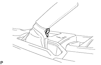
Disengage the 7 claws and 2 clips, and then remove the rear console panel sub-assembly.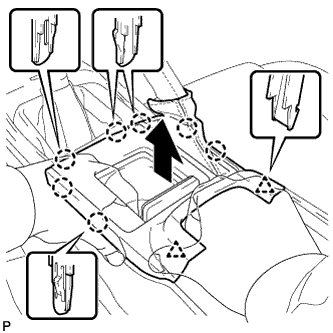
| 4. REMOVE FRONT CONSOLE PANEL SUB-ASSEMBLY |
Open the snap.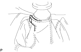
Pull the front console panel sub-assembly in the direction indicated by the arrow to disengage the 6 clips and remove it.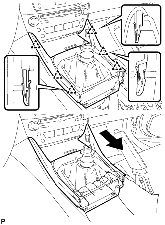
| 5. REMOVE FRONT ASH RECEPTACLE SUB-ASSEMBLY |
Remove the 2 screws <F>.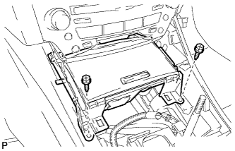
Pull the front ash receptacle sub-assembly in the direction indicated by the arrow to disconnect the connectors and remove it.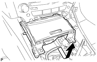
| 6. REMOVE CONSOLE BOX REGISTER ASSEMBLY |
Remove the rear ash receptacle assembly.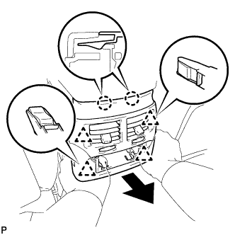
Disengage the 2 claws and 4 clips, and then remove the console box register assembly.
| 7. REMOVE CONSOLE BOX |
Remove the 2 bolts <C>.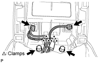
Disconnect the 2 connectors.
Disengage the 2 clamps.
Remove the 2 bolts <C>.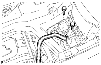
Disconnect the connector.
Remove the 2 bolts <C>.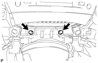
Disengage the 2 claws and 2 clips, and then remove the console box.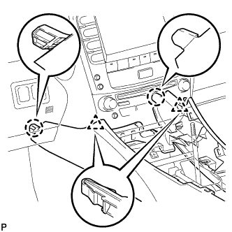
| 8. REMOVE NO. 2 CONSOLE BOX DUCT |
Remove the clip and No. 2 console box duct.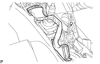
| 9. REMOVE NO. 1 SHIFT AND SELECT LEVER BOOT |
Remove the 4 bolts and No. 1 shift and select lever boot.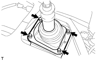
| 10. REMOVE SHIFT LEVER CAP |
Turn over the shift lever dust cover.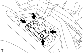
Remove the 4 bolts and shift lever cap.
| 11. REMOVE ENGINE UNDER COVER |
| 12. REMOVE NO. 2 ENGINE UNDER COVER |
| 13. DRAIN MANUAL TRANSMISSION OIL |
Remove the drain plug and gasket, and drain the transmission oil.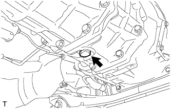
Install a new gasket and the drain plug.
- Torque:
- 37 N*m{ 377 kgf*cm , 27 ft.*lbf }
| 14. REMOVE NO. 1 REAR FLOOR PANEL BRACE |
Remove the 4 bolts and rear No. 1 floor panel brace.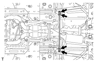
| 15. REMOVE FRONT CENTER FLOOR BRACE |
Remove the 4 bolts and front center floor brace .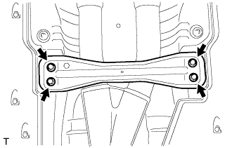
| 16. DISCONNECT HEATED OXYGEN SENSOR |
Remove the grommets of the heated oxygen sensors (BANK 1, BANK 2).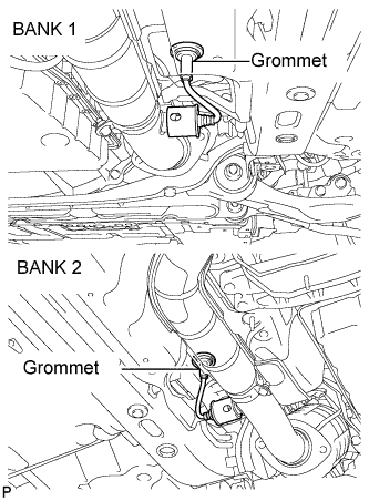
Using the SST, remove a oxygen sensors (BANK 1, BANK 2).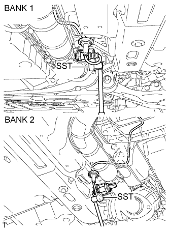
- SST
- 09224-00010
| 17. REMOVE FRONT EXHAUST PIPE ASSEMBLY |
Remove the 4 bolts and 4 nuts.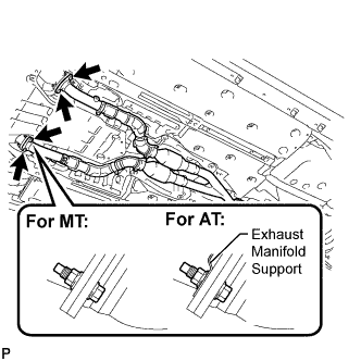
Remove the 2 bolts and 2 compression springs from the tail exhaust pipe assembly.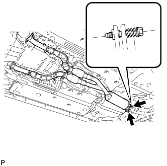
Remove the front exhaust pipe assembly and 3 gaskets.
| 18. REMOVE FRONT FLOOR NO. 1 HEAT INSULATOR |
Remove the 4 nuts and front No. 1 floor heat insulator.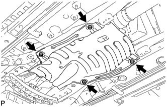
| 19. REMOVE OUTSIDE AIR GUIDE PLATE RH |
Remove the 4 nuts and outside air guide plate RH.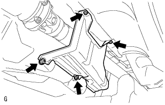
| 20. REMOVE PROPELLER SHAFT WITH CENTER BEARING ASSEMBLY |
Put matchmarks on both flanges.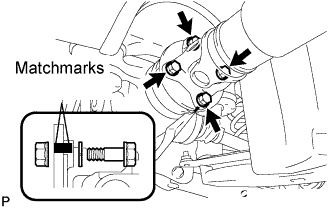
Remove the 4 nuts, bolts and washers.
- HINT:
- If the flange connection is hard to separate, temporarily tighten one nut only and evenly tap the flange with a brass bar and hammer to separate the propeller shaft assembly from the differential companion flange.
Remove the 2 bolts and 2 center support bearing washers. (for automatic transmission)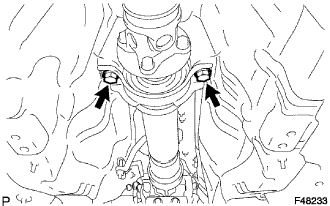
Remove the 2 bolts, 2 center support bearing washers and 2 center support bearing dampers. (for manual transmission)
Separate the center support bearing.
Insert SST in the transmission to prevent oil leakage.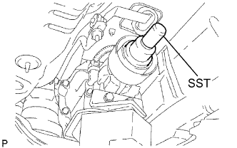
- SST
- 09325-40010
- NOTICE:
- Be careful not to damage the oil seal.
| 21. REMOVE ENGINE UNDER COVER AIR GUIDE BRACKET |
Remove the 2 bolts and engine under cover air guide bracket.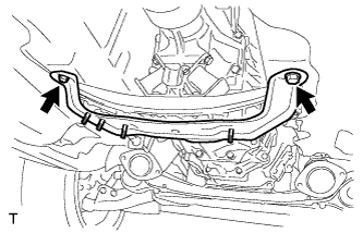
| 22. REMOVE STARTER ASSEMBLY |
| 23. SEPARATE CLUTCH ACCUMULATOR ASSEMBLY |
Remove the 2 bolts and 2 nuts, and separate the clutch accumulator assembly.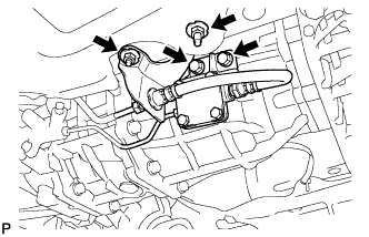
| 24. SEPARATE CLUTCH RELEASE CYLINDER ASSEMBLY |
Remove the 2 bolts and separate the clutch release cylinder assembly.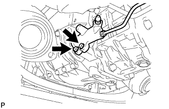
| 25. DISCONNECT GROUND CABLE |
Remove the bolt and disconnect the ground cable.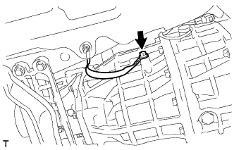
| 26. SEPARATE WIRE HARNESS |
Disconnect the back-up lamp switch connector and separate the wire harness.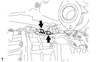
| 27. REMOVE NO. 1 CLUTCH HOUSING COVER |
Remove the 4 bolts and No. 1 clutch housing cover.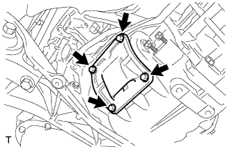
| 28. REMOVE NO. 2 CLUTCH HOUSING COVER |
Remove the 4 bolts and No. 2 clutch housing cover.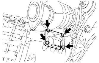
| 29. SEPARATE CLUTCH COVER ASSEMBLY |
Put matchmarks on the clutch cover assembly and the flywheel sub-assembly.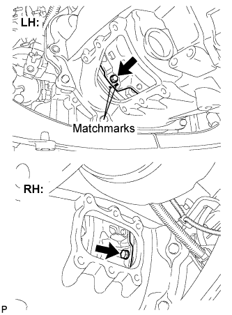
Loosen each set bolt one turn at a time until spring tension is released.
Remove the 6 bolts and separate the clutch cover assembly.
| 30. SEPARATE FLOOR SHIFT CONTROL SHIFT LEVER RETAINER SUB-ASSEMBLY |
Remove the 2 nuts and separate the floor shift control shift lever retainer sub-assembly.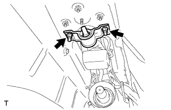
| 31. REMOVE FLOOR SHIFT LEVER ASSEMBLY |
Turn over the shift and select lever boot.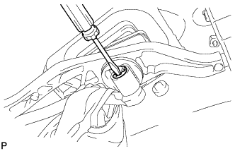
Using a screwdriver, remove the E-ring and floor shift lever assembly.
Remove the washer from the floor shift lever assembly.
Remove the 2 bushings from the floor shift lever assembly.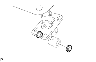
| 32. SUPPORT MANUAL TRANSMISSION ASSEMBLY |
Support the manual transmission with a transmission jack.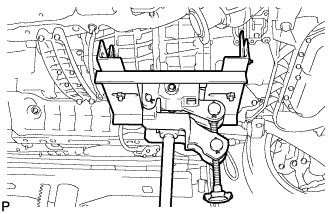
| 33. REMOVE ENGINE REAR MOUNTING MEMBER |
Remove the 4 bolts, 4 nuts and engine rear mounting member.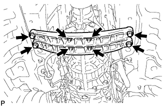
| 34. REMOVE MANUAL TRANSMISSION ASSEMBLY |
Remove the 9 bolts and manual transmission assembly.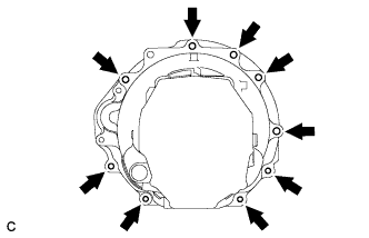
| 35. REMOVE CLUTCH RELEASE FORK SUB-ASSEMBLY |
Remove the clutch release fork sub-assembly from the transmission unit.
| 36. REMOVE CLUTCH DISC ASSEMBLY |
- NOTICE:
- Keep the lining part of the clutch disc assembly, the pressure plate and surface of the flywheel sub-assembly away from oil and foreign matter.
| 37. REMOVE CLUTCH COVER ASSEMBLY |
| 38. REMOVE REAR NO. 1 ENGINE MOUNTING INSULATOR |
Remove the 4 bolts and rear No. 1 engine mounting insulator.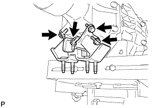
| 39. REMOVE TRANSMISSION UPPER COVER SUB-ASSEMBLY |
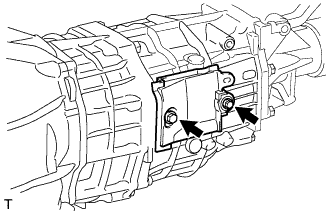
Remove the 2 bolts and transmission upper cover sub-assembly.