Entry Lock Switch Circuit
Circuit diagnosis
DESCRIPTION
The entry lock switches (trigger switch) are built into the outside handles of the LH/RH door. The certification ECU detects the conditions of the each lock switch.WIRING DIAGRAM
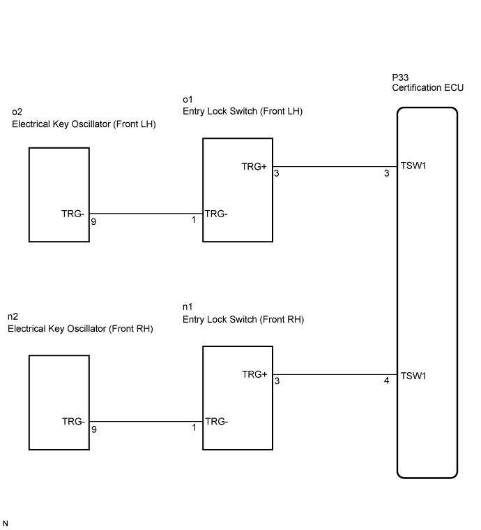

INSPECTION PROCEDURE
| 1. INSPECT ENTRY LOCK SWITCH |

Remove the outside handle.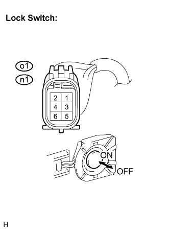
Disconnect the connectors.
Measure the resistance according to the value(s) in the table below.
- Standard resistance:
Tester Connection (Symbols)
Condition
Specified Condition
o1-1 (TRG-) - o1-3 (TRG+)
Lock switch not pushed
10 kΩ or higher
Lock switch pushed
Below 1 Ω
n1-1 (TRG-) - n1-3 (TRG+)
Lock switch not pushed
10 kΩ or higher
Lock switch pushed
Below 1 Ω
|
|
||||

| OK | |
 |
| 2. CHECK HARNESS AND CONNECTOR (CERTIFICATION ECU - ENTRY LOCK SWITCH) |
Disconnect the P33 ECU connector.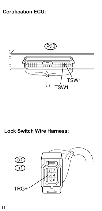
Measure the resistance according to the value(s) in the table below.
- Standard resistance:
Tester Connection (Symbols)
Condition
Specified Condition
P33-3 (TSW1) - o1-3 (TRG+)
Always
Below 1 Ω
P33-4 (TSW1) - n1-3 (TRG+)
Always
Below 1 Ω
P33-3 (TSW1) - Body ground
Always
10 kΩ or higher
P33-4 (TSW1) - Body ground
Always
10 kΩ or higher
|
|
||||
| OK | |
|
| 3. CHECK HARNESS AND CONNECTOR (ELECTRICAL KEY OSCILLATOR - ENTRY LOCK SWITCH) |
Disconnect the door oscillator connector.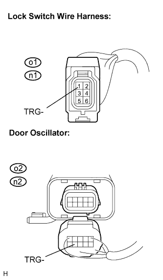
Measure the resistance according to the value(s) in the table below.
- Standard resistance:
Tester Connection
(Symbols)
Condition
Specified condition
o2-9 (TRG-) - o1-1 (TRG-)
Always
Below 1 Ω
n2-9 (TRG-) - n1-1 (TRG-)
Always
Below 1 Ω
o2-9 (TRG-) - Body ground
Always
10 kΩ or higher
n2-9 (TRG-) - Body ground
Always
10 kΩ or higher
|
|
||||
| OK | |
|
| 4. CHECK AND REPLACE ELECTRICAL KEY OSCILLATOR |
Replace the electrical key oscillator.
Check that the entry LOCK / UNLOCK function operates normally.
- OK:
- Entry LOCK / UNLOCK function operates normally.
|
|
||||
| OK | ||
 |
||
| ||