Mirror Heater does not Operate with Rear Defogger Switch
Circuit diagnosis
DESCRIPTION
- with Navigation System:
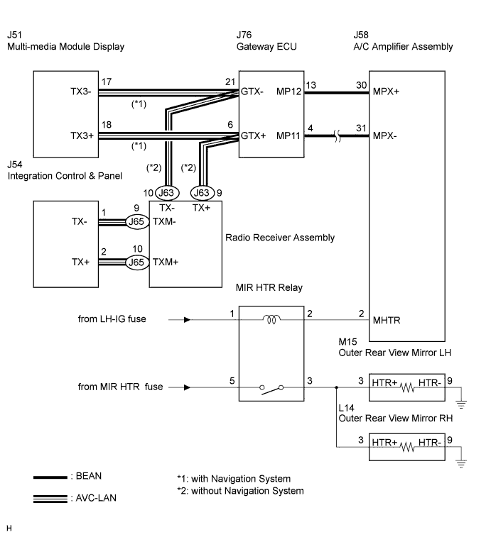
- When the mirror defogger switch, which is built into the multi-media module display assembly, is operated, the operation signals are transmitted to the A/C amplifier assembly through AVC-LAN and BEAN. When the A/C amplifier assembly receives the signals, it turns on the MIR HTR relay to operate the mirror defogger.
- without Navigation System:
- When the mirror defogger switch, which is built into the integration control & panel, is operated, the operation signals are transmitted to the A/C amplifier assembly through AVC-LAN and BEAN. When the A/C amplifier assembly receives the signals, it turns on the MIR HTR relay to operate the mirror defogger.
WIRING DIAGRAM

INSPECTION PROCEDURE
| 1. CHECK DTCs |

Select the DTC check on the intelligent tester to check for communication errors.
- Result:
Not output DTC codes
A
Output DTC codes (Multiplex communication)
B
Output DTC codes (CAN communication)
C
|
|
||||
|
|
||||

| A | |
 |
| 2. PERFORM ACTIVE TEST BY INTELLIGENT TESTER |
Select the ACTIVE TEST, use the intelligent tester to issue a control command, and then check the mirror defogger operation.
- Air Conditioner:
Item
Test Details
Mirror Heater
Mirror heater operation: OFF/ON
- Result:
OK (with Navigation System)
A
OK (without Navigation System)
B
NG
C
|
|
||||
|
|
||||

| A | |
|
| 3. REPLACE MULTI-MEDIA MODULE DISPLAY |
Replace the multi-media module display.
| NEXT | |
|
| 4. CONFIRM MIRROR DEFOGGER OPERATION |
Turn the engine switch on (IG), press the defogger switch, and check that mirror heater operates.
|
|
||||
| OK | ||
 |
||
| ||
| 5. REPLACE INTEGRATION CONTROL & PANEL |
Replace the integration control & panel.
| NEXT | |
|
| 6. CONFIRM MIRROR DEFOGGER OPERATION |
Turn the engine switch on (IG), press the defogger switch, and check that mirror heater operates.
|
|
||||
| NG | |
|
| 7. REPLACE RADIO RECEIVER ASSEMBLY |
Replace the radio receiver assembly.
| NEXT | |
|
| 8. CONFIRM MIRROR DEFOGGER OPERATION |
Turn the engine switch on (IG), press the defogger switch, and check that mirror heater operates.
|
|
||||
| OK | ||
|
||
| ||
| 9. PERFORM ACTIVE TEST BY INTELLIGENT TESTER |
Select the ACTIVE TEST, use the intelligent tester to issue a control command, and then check the MIR HTR relay operation.
- HINT:
- Check that operation sound of the MIR HTR relay can be heard.
|
|
||||
| NG | |
|
| 10. INSPECT MIR HTR RELAY |
|
|
||||
| OK | |
|
| 11. CHECK WIRE HARNESS (MIR HTR RELAY) |
Disconnect the MIR HTR relay.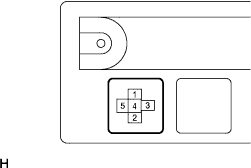
Measure the voltage according to the value(s) in the table below.
- Voltage:
Tester Connection
Condition
Specified Condition
1 - Body ground
Engine switch on (IG)
10 to 14 V
|
|
||||
| OK | |
|
| 12. CHECK WIRE HARNESS (MIR HTR RELAY - A/C AMPLIFIER ASSEMBLY) |
Disconnect the MIR HTR relay and A/C amplifier assembly connector.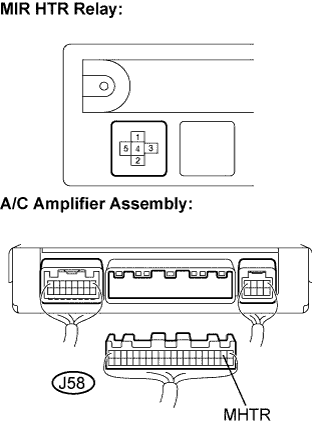
Measure the resistance according to the value(s) in the table below.
- Resistance:
Tester Connection
Condition
Specified Condition
2 - J58-2 (MHTR)
Always
Below 1 Ω
2 - Body ground
Always
10 kΩ or higher
|
|
||||
| OK | ||
|
||
| ||
| 13. INSPECT MIR HTR RELAY |
|
|
||||
| OK | |
|
| 14. CHECK WIRE HARNESS (MIR HTR RELAY - BATTERY POSITIVE AND BODY GROUND) |
Disconnect the MIR HTR relay.
Measure the voltage according to the value(s) in the table below.
- Voltage:
Tester Connection
Condition
Specified Condition
5 - Body ground
Engine switch on (IG)
10 to 14 V
|
|
||||
| OK | |
|
| 15. CHECK WIRE HARNESS (MIR HTR RELAY - OUTER MIRROR ASSEMBLY) |
Disconnect the MIR HTR relay and outer rear view mirror assembly connectors.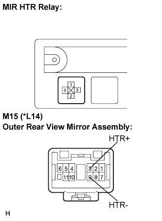
Measure the resistance according to the value(s) in the table below.(*): Outer rear view mirror assembly RH
- Resistance:
- Outer rear view mirror assembly LH:
Tester Connection
Condition
Specified Condition
3 - M15-3 (HTR+)
Always
Below 1 Ω
3 - Body ground
Always
10 kΩ or higher
M15-9 (HTR-) - Body ground
Always
Below 1 Ω
- Outer rear view mirror assembly RH:
Tester Connection
Condition
Specified Condition
3 - L14-3 (HTR+)
Always
Below 1 Ω
3 - Body ground
Always
10 kΩ or higher
L14-9 (HTR-) - Body ground
Always
Below 1 Ω
|
|
||||
| OK | ||
|
||
| ||