Power Mirror cannot be Adjusted with Power Mirror Switch
Circuit diagnosis
DESCRIPTION
- A switch signal of the outer mirror switch is transmitted to the selected outer mirror control ECU by way of the main body ECU RH. Then, the outer mirror control ECU activates the mirror motor to move the mirror UP, DOWN, RIGHT and LEFT in response to the input.
- Mirror control switch and memorized mirror position signals (from the position control ECU & switch (seat ECU)) are sent to the mirror control ECU. The mirror control ECU moves the selected mirror UP, DOWN, LEFT and RIGHT in response to the input.
- HINT:
- The power mirror control system is a part of the multiplex communication system. This system features shared communication wiring that reduces the wiring complexity of the communication lines. The first step in any repair is to confirm the proper operation of the communication system. Proceed with troubleshooting after the communication has been verified (See the Multiplex Communication System).
WIRING DIAGRAM
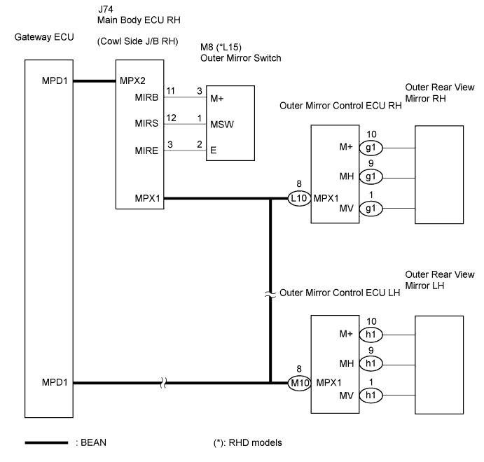

INSPECTION PROCEDURE
| 1. CHECK DTCs |

Select the DTC check on the intelligent tester to check for communication errors.
- Result:
Not output DTC codes
A
Output DTC codes
B
|
|
||||

| A | |
 |
| 2. INSPECT OUTER MIRROR SWITCH |
Remove the outer mirror switch.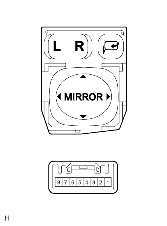
Measure the resistance according to the value(s) in the table below when the switch is operated.
- Resistance:
Tester Connection
Switch Position
Specified Condition
2 - 3
OFF
10 kΩ or higher
UP
225 to 275 Ω
DOWN
437 to 503 Ω
LEFT
744 to 856 Ω
RIGHT
437 to 503 Ω
1 - 2
L
90 to 110 Ω
R
10 Ω or less
|
|
||||
| OK | |
|
| 3. CHECK WIRE HARNESS (OUTER MIRROR SWITCH - MAIN BODY ECU RH) |
Disconnect the M8 (*L15) and J74 connectors.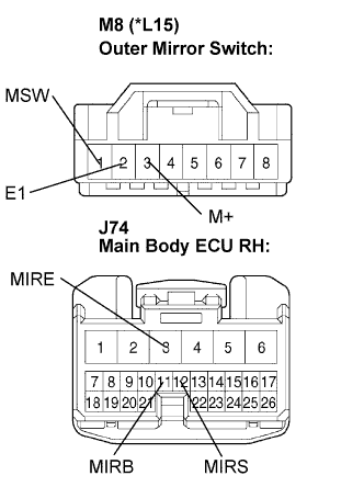
Measure the resistance according to the value(s) in the table below.( *): RHD models
- Resistance:
- LHD models:
Tester Connection
Condition
Specified Condition
M8-3 (M+) - J74-11 (MIRB)
Always
Below 1 Ω
M8-1 (MSW) - J74-12 (MIRS)
Always
Below 1 Ω
M8-2 (E) - J74-3 (MIRE)
Always
Below 1 Ω
M8-3 (M+) - Body ground
Always
10 kΩ or higher
M8-1 (MSW) - Body ground
Always
10 kΩ or higher
M8-2 (E) - Body ground
Always
10 kΩ or higher
- RHD models:
Tester Connection
Condition
Specified Condition
L15-3 (M+) - J74-11 (MIRB)
Always
Below 1 Ω
L15-1 (MSW) - J74-12 (MIRS)
Always
Below 1 Ω
L15-2 (E) - J74-3 (MIRE)
Always
Below 1 Ω
L15-3 (M+) - Body ground
Always
10 kΩ or higher
L15-1 (MSW) - Body ground
Always
10 kΩ or higher
L15-2 (E) - Body ground
Always
10 kΩ or higher
|
|
||||
| OK | ||
 |
||
| ||
| 4. PERFORM ACTIVE TEST BY INTELLIGENT TESTER |
Select the ACTIVE TEST, use the intelligent tester to issue a control command, and then check the outer rear view mirrors.
- Mirror-L/Mirror-R:
Item
Test Details
Mirror Up/Down
Mirror vertical operation: UP/DOWN
Mirror Right/Left
Mirror horizontal operation: RIGHT/LEFT
|
|
||||
| NG | |
|
| 5. INSPECT OUTER REAR VIEW MIRROR ASSEMBLY |
Outer rear view mirror LH:Disconnect the h1 connector.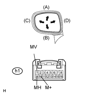
Apply battery voltage and check operation of the mirror face.
- Standard:
Measurement Condition
Mirror Operation
Battery positive (+) → h1-1 (MV)
Battery negative (-) → h1-10 (M+)
Turns upward (A)
Battery positive (+) → h1-10 (M+)
Battery negative (-) → h1-1 (MV)
Turns downward (B)
Battery positive (+) → h1-9 (MH)
Battery negative (-) → h1-10 (M+)
Turns left (C)
Battery positive (+) → h1-10 (M+)
Battery negative (-) → h1-9 (MH)
Turns right (D)
Outer rear view mirror RH:Disconnect the g1 connector.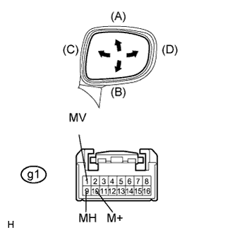
Apply battery voltage and check operation of the mirror face.
- Standard:
Measurement Condition
Mirror Operation
Battery positive (+) → g1-1 (MV)
Battery negative (-) → g1-10 (M+)
Turns upward (A)
Battery positive (+) → g1-10 (M+)
Battery negative (-) → g1-1 (MV)
Turns downward (B)
Battery positive (+) → g1-9 (MH)
Battery negative (-) → g1-10 (M+)
Turns left (C)
Battery positive (+) → g1-10 (M+)
Battery negative (-) → g1-9 (MH)
Turns right (D)
|
|
||||
| OK | ||
|
||
| ||