| Last Modified: 11-27-2007 | 1.6 A | |
| Service Category: Engine/Hybrid System | Section: Fuel System | |
| Model Year: 2008 | Model: LX570 | Doc ID: RM000000Q4602FX |
| Title: 3UR-FE FUEL: FUEL INJECTOR: INSTALLATION (2008 LX570) | ||
INSTALLATION
1. INSTALL FUEL INJECTOR ASSEMBLY
|
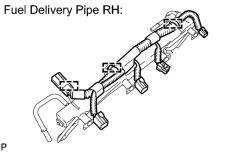
(a) Attach the 3 clamps to install the No. 6 wire harness to the delivery pipe RH. |
|
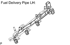
(b) Attach the 3 clamps to install the No. 7 wire harness to the delivery pipe LH. |
|
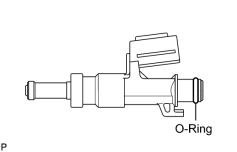
(c) Apply gasoline or spindle oil to a new O-ring and install it to the injector. NOTICE:
Make sure that there is no damage or foreign material in the groove of the injector when installing the O-ring. |
|
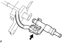
(d) Connect the injector connector. |
|
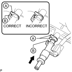
(e) Install the injector to the delivery pipe as shown in the illustration. NOTICE:
|
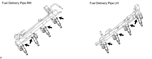
(f) Check that each injector is installed to the delivery pipe facing the direction shown in the illustration.
2. INSTALL FUEL DELIVERY PIPE SUB-ASSEMBLY LH
|
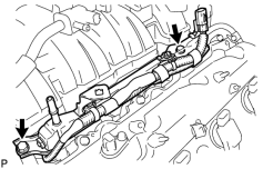
(a) Install the 2 delivery pipe spacers and 4 insulators to the cylinder head LH. |
(b) Install the delivery pipe (with injectors) to the cylinder head LH.
(c) Install the 2 bolts.
Torque: 21 N·m (214 kgf·cm, 15 ft·lbf)
NOTICE:
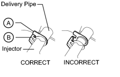
Make sure that the part of the injector labeled B is between the parts of the delivery pipe labeled A.
(d) Connect the No. 7 wire harness connector.
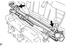
3. INSTALL FUEL DELIVERY PIPE SUB-ASSEMBLY RH
|
(a) Install the 2 delivery pipe spacers and 4 insulators to the cylinder head RH. |
(b) Install the delivery pipe (with injectors) to the cylinder head RH.
(c) Install the 2 bolts.
Torque: 21 N·m (214 kgf·cm, 15 ft·lbf)
NOTICE:
Make sure that the part of the injector labeled B is between the parts of the delivery pipe labeled A.
|
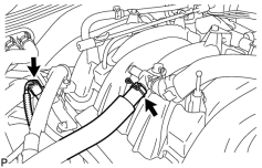
(d) Connect the No. 6 wire harness connector. |
(e) Connect the ventilation hose.
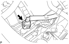
4. CONNECT NO. 1 FUEL HOSE
|
(a) Connect the No. 1 fuel hose to the fuel delivery pipe LH
|
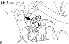
5. CONNECT NO. 1 FUEL TUBE
|
(a) LH Side: Connect the No. 1 fuel tube to the delivery pipe LH
|
|
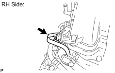
(b) RH Side: Connect the No. 1 fuel tube to the delivery pipe RH
|
6. CONNECT NO. 2 FUEL TUBE
|
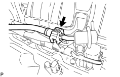
(a) Connect the No. 2 fuel tube to the fuel pressure regulator
|
7. INSTALL NO. 1 ENGINE COVER SUB-ASSEMBLY
|
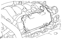
(a) Install the No. 1 engine cover sub-assembly. |
8. INSTALL NO. 3 ENGINE COVER
|
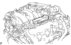
(a) Install the No. 3 engine cover. |
9. INSTALL AIR CLEANER HOSE ASSEMBLY

10. CONNECT CABLE TO NEGATIVE BATTERY TERMINAL
NOTICE:
When disconnecting the cable, some systems need to be initialized after the cable is reconnected
.
11. INSPECT FOR FUEL LEAK
(a) Connect the Techstream to the DLC3.
(b) Turn the engine switch on (IG) and Techstream main switch on.
NOTICE:
Do not start the engine.
(c) Enter the following menus: Powertrain / Engine and ECT / Active Test / Control the Fuel Pump / Speed.
(d) Check that there are no fuel leaks after doing maintenance anywhere on the fuel system.
12. INSTALL V-BANK COVER SUB-ASSEMBLY
13. INSTALL UPPER RADIATOR SUPPORT SEAL
14. INSTALL ENGINE ROOM SIDE COVER LH
15. INSTALL ENGINE ROOM SIDE COVER RH

|

|