| Last Modified: 11-27-2007 | 1.6 A | |
| Service Category: Engine/Hybrid System | Section: Intake/Exhaust | |
| Model Year: 2008 | Model: LX570 | Doc ID: RM0000031GO005X |
| Title: 3UR-FE INTAKE / EXHAUST: INTAKE MANIFOLD: INSTALLATION (2008 LX570) | ||
INSTALLATION
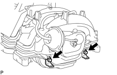
1. INSTALL WIRE HARNESS CLAMP BRACKET
|
(a) Install the 2 wire harness clamp brackets with the 2 bolts. Torque: 8.0 N·m (82 kgf·cm, 71 in·lbf) |
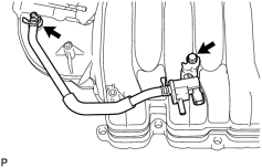
2. INSTALL PURGE VSV
|
(a) Connect the purge line hose to the intake manifold. |
(b) Install the purge VSV to the intake manifold with the bolt.
Torque: 21 N·m (214 kgf·cm, 15 ft·lbf)
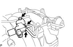
3. INSTALL VACUUM SWITCHING VALVE ASSEMBLY (for ACIS)
|
(a) Install the vacuum switching valve to the intake manifold with the bolt. Torque: 9.0 N·m (92 kgf·cm, 80 in·lbf) |
(b) Connect the 2 vacuum hoses to the vacuum switching valve.
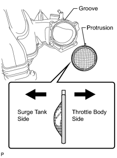
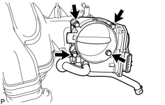
4. INSTALL THROTTLE BODY ASSEMBLY
|
(a) Align the protrusion of a new gasket with the groove of the intake manifold, and install the gasket. |
|
(b) Install the throttle body with the 4 bolts. Torque: 10 N·m (102 kgf·cm, 7 ft·lbf) |
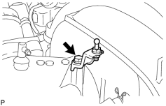
5. INSTALL NO. 2 V-BANK COVER BRACKET SUB-ASSEMBLY
|
(a) Install the bracket with the bolt. Torque: 10 N·m (102 kgf·cm, 7 ft·lbf) |
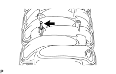
6. INSTALL V-BANK COVER BOLT
|
(a) Install the cover bolt to the intake manifold. Torque: 10 N·m (102 kgf·cm, 7 ft·lbf) |
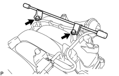
7. INSTALL NO. 1 V-BANK COVER BRACKET
|
(a) Install the bracket with the 2 bolts. Torque: 10 N·m (102 kgf·cm, 7 ft·lbf) |
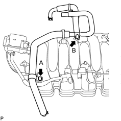
8. INSTALL VENTILATION HOSE ASSEMBLY
|
(a) Install the ventilation hose to the intake manifold with the 2 bolts. Torque: 21 N·m (214 kgf·cm, 15 ft·lbf) Torque: 10 N·m (102 kgf·cm, 7 ft·lbf) |
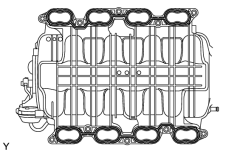
9. INSTALL INTAKE MANIFOLD
|
(a) Place 2 new gaskets on the intake manifold. |
(b) Place the intake manifold on the cylinder head.
|
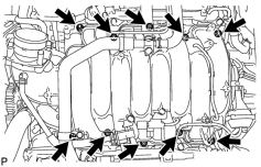
(c) Install and uniformly tighten the 8 bolts and 2 nuts in several steps. Torque: 21 N·m (214 kgf·cm, 15 ft·lbf) |
|
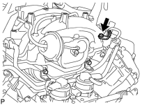
(d) Install the wire bracket to the intake manifold with the bolt. Torque: 8.0 N·m (82 kgf·cm, 71 in·lbf) |
|
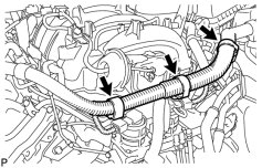
(e) Connect the 3 wire clamps to the 3 wire brackets. |
|
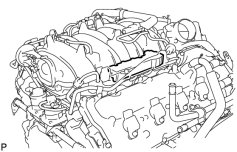
(f) Install the No. 3 engine cover. |
|
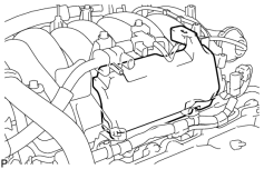
(g) Install the No. 1 engine cover sub-assembly. |
|
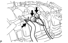
(h) Connect the purge VSV connector. |
(i) Connect the purge line hose to the purge VSV.
(j) Connect the vacuum switching valve connector (for ACIS).
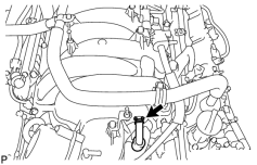
|
(k) Connect the No. 1 ventilation hose. |
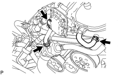
|
(l) Connect the 2 water by-pass hoses. |
(m) Connect the throttle body connector.
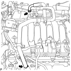
|
(n) Connect the ventilation hose to the ventilation pipe of the cylinder head cover LH and RH. |
10. INSTALL AIR CLEANER HOSE ASSEMBLY
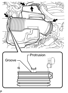
|
(a) Install the air cleaner hose so that the protrusion of the air cleaner cap aligns with the groove of the hose as shown in the illustration. |
(b) Tighten the 2 clamps.
Torque: 5.0 N·m (51 kgf·cm, 44 in·lbf)
(c) Connect the vacuum hose.
(d) Connect the No. 2 ventilation hose.
11. ADD ENGINE COOLANT

12. INSPECT FOR COOLANT LEAK
13. INSTALL NO. 1 ENGINE UNDER COVER SUB-ASSEMBLY
14. INSTALL FRONT FENDER SPLASH SHIELD SUB-ASSEMBLY LH
15. INSTALL FRONT FENDER SPLASH SHIELD SUB-ASSEMBLY RH
16. INSTALL COWL TOP VENTILATOR LOUVER SUB-ASSEMBLY
(a) Install the cowl top ventilator louver
.
17. CONNECT CABLE TO NEGATIVE BATTERY TERMINAL
NOTICE:
When disconnecting the cable, some systems need to be initialized after the cable is reconnected
.
18. CHECK THROTTLE BODY ASSEMBLY
19. INSTALL V-BANK COVER SUB-ASSEMBLY
20. INSTALL UPPER RADIATOR SUPPORT SEAL
21. INSTALL ENGINE ROOM SIDE COVER LH
22. INSTALL ENGINE ROOM SIDE COVER RH

|

|