| Last Modified: 11-27-2007 | 1.6 J | |
| Service Category: Drivetrain | Section: Automatic Transmission/Transaxle | |
| Model Year: 2008 | Model: LX570 | Doc ID: RM000000YTG01RX |
| Title: AB60F AUTOMATIC TRANSMISSION / TRANSAXLE: AUTOMATIC TRANSMISSION SYSTEM: DESCRIPTION (2008 LX570) | ||
|
Pattern Select Switch 2nd Start Mode Circuit |
DESCRIPTION
When 2nd mode is selected with the No. 1 pattern select switch assembly, the ECM controls the shift solenoid valves and the transmission starts from 2nd gear.
The 2nd mode is the system that operates the throttle motor to control engine output to reduce skidding of the driving wheels, and guarantee takeoff acceleration, driving straightness and turning stability.
When the shift lever is in D, the transmission automatically shifts up through 3rd to 6th as usual.
WIRING DIAGRAM
Refer to Pattern Select Switch Power Mode Circuit
 .
.
INSPECTION PROCEDURE
When the pattern select switch (2ND) is pushed, switch contact is made and 2nd mode is selected. To cancel 2nd mode, push the pattern select switch (2ND) once again.
HINT:
2nd mode is automatically canceled when the engine switch is turned off.
PROCEDURE
|
1. |
DRIVING TEST |
HINT:
The driving test should be performed on a paved road (nonskid road).
(a) Start the engine.
(b) Turn the 2ND switch off (normal drive mode).
(c) Confirm vehicle response by driving from a parked position to fully depressing the accelerator pedal.
(d) Turn the 2ND switch on and perform the same check as above.
When driving the vehicle with the 2ND switch on and off, check that there is a difference in acceleration.
OK:
There is a difference in acceleration.
|

|
3. |
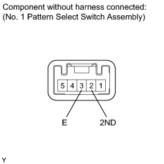
INSPECT NO. 1 PATTERN SELECT SWITCH ASSEMBLY (2ND) |
|
(a) Remove the No. 1 pattern select switch assembly
|
(b) Measure the resistance according to the value(s) in the table below.
Standard Resistance:
|
Tester Connection |
Switch Condition |
Specified Condition |
|---|---|---|
|
2 (2ND) - 3 (E) |
Pattern select switch (2ND) and held pressed |
Below 1 Ω |
|
2 (2ND) - 3 (E) |
Pattern select switch (2ND) released |
10 kΩ or higher |
|
|
4. |
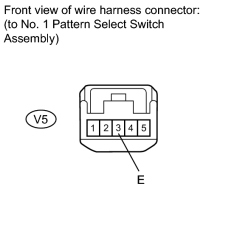
CHECK HARNESS AND CONNECTOR (NO. 1 PATTERN SELECT SWITCH ASSEMBLY - BODY GROUND) |
|
(a) Disconnect the V5 No. 1 pattern select switch assembly connector. |
(b) Measure the resistance according to the value(s) in the table below.
Standard Resistance:
|
Tester Connection |
Condition |
Specified Condition |
|---|---|---|
|
V5-3 (E) - Body ground |
Always |
Below 1 Ω |
|
|
5. |
CHECK HARNESS AND CONNECTOR (NO. 1 PATTERN SELECT SWITCH ASSEMBLY - ECM) |
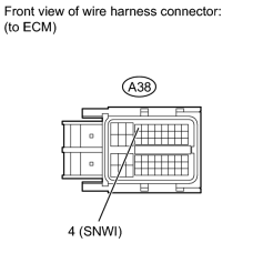
(a) Disconnect the A38 ECM connector.
(b) Measure the resistance according to the value(s) in the table below.
Standard Resistance:
|
Tester Connection |
Switch Condition |
Specified Condition |
|---|---|---|
|
A38-4 (SNWI) - Body ground |
Pattern select switch (2ND) pressed and held |
Below 1 Ω |
|
A38-4 (SNWI) - Body ground |
Pattern select switch (2ND) released |
10 kΩ or higher |
|

|

|