| Last Modified: 11-27-2007 | 1.6 U | |
| Service Category: Audio/Visual/Telematics | Section: Navigation/Multi Info Display | |
| Model Year: 2008 | Model: LX570 | Doc ID: RM0000011BQ02UX |
| Title: NAVIGATION / MULTI INFO DISPLAY: NAVIGATION SYSTEM: TERMINALS OF ECU (2008 LX570) | ||
TERMINALS OF ECU
1. CHECK DISPLAY AND NAVIGATION MODULE DISPLAY
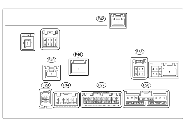
(a) Disconnect the F28 display connector.
(b) Measure the resistance and voltage according to the value(s) in the table below.
|
Terminal No. (Symbol) |
Wiring Color |
Terminal Description |
Condition |
Specified Condition |
|---|---|---|---|---|
|
F28-1 (+B1) - F28-10 (GND1) |
R - W-B |
Battery |
Always |
11 to 14 V |
|
F28-2 (ACC) - F28-10 (GND1) |
GR - W-B |
Accessory (ON) |
Engine switch off |
Below 1 V |
|
F28-2 (ACC) - F28-10 (GND1) |
GR - W-B |
Accessory (ON) |
Engine switch on (ACC) |
11 to 14 V |
|
F28-3 (IG) - F28-10 (GND1) |
G - W-B |
Ignition (ON) |
Engine switch off |
Below 1 V |
|
F28-3 (IG) - F28-10 (GND1) |
G - W-B |
Ignition (ON) |
Engine switch on (IG) |
11 to 14 V |
|
F28-10 (GND1) - Body ground |
W-B - Body ground |
Ground |
Always |
Below 1 Ω |
If the result is not as specified, there may be a malfunction on the wire harness side.
(c) Reconnect the F28 display connector.
(d) Measure the voltage according to the value(s) in the table below.
|
Terminal No. (Symbol) |
Wiring Color |
Terminal Description |
Condition |
Specified Condition |
|---|---|---|---|---|
|
F27-1 (TX-) - F28-10 (GND1) |
L - W-B |
AVC-LAN communication signal |
Engine switch on (ACC) |
2 to 3 V |
|
F27-2 (TX+) - F28-10 (GND1) |
W - W-B |
AVC-LAN communication signal |
Engine switch on (ACC) |
2 to 3 V |
|
F27-3 (TX2-) - F28-10 (GND1) |
L - W-B |
AVC-LAN communication signal |
Engine switch on (ACC) |
2 to 3 V |
|
F27-4 (TX2+) - F28-10 (GND1) |
W - W-B |
AVC-LAN communication signal |
Engine switch on (ACC) |
2 to 3 V |
|
F27-5 (TSW-) - F28-10 (GND1) |
BR - W-B |
Telephone relation switch signal |
Always |
Below 1 V |
|
F27-9 (MACC) - F28-10 (GND1)*1 |
Y - W-B |
Microphone amplifier power supply |
Engine switch off |
Below 1 V |
|
F27-9 (MACC) - F28-10 (GND1)*1 |
Y - W-B |
Microphone amplifier power supply |
Engine switch on (IG) |
5 V |
|
F27-10 (MIN-) - F28-10 (GND1) |
R - W-B |
Microphone voice signal |
See "Microphone & Voice Recognition Check"
|
- |
|
F27-11 (MIN+) - F28-10 (GND1) |
G - W-B |
Microphone voice signal |
See "Microphone & Voice Recognition Check"
|
- |
|
F27-12 (SGND) - F28-10 (GND1) |
BR - W-B |
Signal ground |
Always |
Below 1 V |
|
F27-13 (CA+) - F28-10 (GND1)*2 |
B - W-B |
Television camera power supply |
Engine switch on (IG), shift lever moved to R |
5.8 to 6.5 V |
|
F27-14 (CGND) - Body ground*2 |
W - Body ground |
Ground |
Always |
Below 1 V |
|
F27-21 (IVO-) - F28-10 (GND1) |
B - W-B |
Voice guidance signal |
Voice guidance provided |
Waveform synchronized with sounds is output |
|
F27-22 (IVO+) - F28-10 (GND1) |
W - W-B |
Voice guidance signal |
Voice guidance provided |
Waveform synchronized with sounds is output |
|
F27-23 (SLD) - F28-10 (GND1) |
Shielded - W-B |
Shielded ground |
Always |
Below 1 V |
|
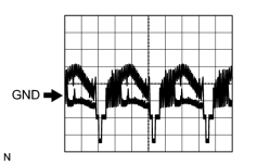
F27-27 (V+) - F27-28 (V-)*2 |
R - W |
Television camera image signal |
Engine switch on (IG), shift lever moved to R |
Pulse generation (refer to waveform 1) |
|
F27-28 (V-) - F27-14 (CGND)*2 |
Shielded - W |
Shielded ground |
Always |
Below 1 V |
|
F28-5 (HILL) - F28-10 (GND1) |
W - W-B |
Illumination signal |
Light control switch off |
Below 1 V |
|
F28-5 (HILL) - F28-10 (GND1) |
W - W-B |
Illumination signal |
Light control switch on |
11 to 14 V |
|
F28-7 (TC) - F28-10 (GND1) |
V - W-B |
Diagnosis ON signal |
Engine switch on (IG) |
9 to 14 V |
|
F28-8 (HAZ) - F28-10 (GND1) |
O - W-B |
Hazard warning signal |
Hazard warning switch off |
Below 1 V |
|
Hazard warning switch on |
11 to 14 V |
|||
|
F28-9 (ARON) - F28-10 (GND1) |
W - W-B |
Front passenger side airbag ON/OFF indicator signal |
Passenger airbag ON/OFF indicator off |
Below 2 V |
|
Passenger airbag ON/OFF indicator on |
11 to 14 V |
|||
|
F28-12 (ILL+) - F28-10 (GND1) |
G - W-B |
Illumination signal |
Light control switch off |
Below 1 V |
|
F28-12 (ILL+) - F28-10 (GND1) |
G - W-B |
Illumination signal |
Light control switch on |
11 to 14 V |
|
F28-13 (REV) - F28-10 (GND1) |
L - W-B |
Reverse signal |
See "Vehicle Signal Check" Mode
|
- |
|
F28-14 (SPD) - F28-10 (GND1) |
V - W-B |
Speed signal from combination meter |
See "Vehicle Signal Check" Mode
|
- |
|
F28-20 (AIR) - F28-10 (GND1) |
B - W-B |
Front passenger side airbag ON/OFF indicator signal |
Passenger airbag ON/OFF indicator off |
Below 2 V |
|
Passenger airbag ON/OFF indicator on |
10.5 to 16 V |
|||
|
F28-21 (PBEW) - F28-10 (GND1) |
Y - W-B |
Passenger seat belt signal |
Passenger seat occupied, seat belt fastened |
11 to 14 V |
|
Passenger seat occupied, seat belt unfastened |
Below 2 V |
|||
|
F28-23 (PKB) - F28-10 (GND1) |
Y - W-B |
Parking brake signal |
See "Vehicle Signal Check" Mode
|
- |
|
F28-24 (HFOF) - F28-10 (GND1) |
B - W-B |
Phone mute |
Engine switch on (IG) |
3.3 to 5.0 V |
|
F29-1 (VV+) - F28-10 (GND1) |
W - W-B |
DVD image signal |
DVD played on radio receiver |
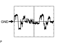
Pulse generation (refer to waveform 2) |
|
F29-4 (VV-) - F28-10 (GND1) |
B - W-B |
Signal ground |
Always |
Below 1 V |
|
F34-1 (FR+) - F28-10 (GND1)*3 |
B - W-B |
Sound signal (right) |
Engine switch on (ACC), audio system playing |
Waveform synchronized with sounds is output |
|
F34-2 (FR-) - F28-10 (GND1)*3 |
W - W-B |
Sound signal (right) |
Engine switch on (ACC), audio system playing |
Waveform synchronized with sounds is output |
|
F34-3 (FL+) - F28-10 (GND1)*3 |
L - W-B |
Sound signal (left) |
Engine switch on (ACC), audio system playing |
Waveform synchronized with sounds is output |
|
F34-4 (FL-) - F28-10 (GND1)*3 |
R - W-B |
Sound signal (left) |
Engine switch on (ACC), audio system playing |
Waveform synchronized with sounds is output |
|
F34-5 (SLD1) - F28-10 (GND1)*3 |
Shielded - W-B |
Shielded ground |
Always |
Below 1 V |
|
F34-7 (MUT2) - F28-10 (GND1)*3 |
B - W-B |
Mute signal |
Sound library playing → Changing mode |
3.5 V or higher → Below 1 V |
|
F34-8 (MUTE) - F28-10 (GND1)*3 |
G - W-B |
Mute signal |
Sound library playing → Changing mode |
3.5 V or higher → Below 1 V |
|
F34-9 (RL-) - F28-10 (GND1)*3 |
G - W-B |
Sound signal (right) |
Engine switch on (ACC), audio system playing |
Waveform synchronized with sounds is output |
|
F34-10 (RL+) - F28-10 (GND1)*3 |
R - W-B |
Sound signal (right) |
Engine switch on (ACC), audio system playing |
Waveform synchronized with sounds is output |
|
F34-11 (RR-) - F28-10 (GND1)*3 |
W - W-B |
Sound signal (left) |
Engine switch on (ACC), audio system playing |
Waveform synchronized with sounds is output |
|
F34-12 (RR+) - F28-10 (GND1)*3 |
B - W-B |
Sound signal (left) |
Engine switch on (ACC), audio system playing |
Waveform synchronized with sounds is output |
|
F34-13 (SGD2) - F28-10 (GND1)*3 |
Shielded - W-B |
Shielded ground |
Always |
Below 1 V |
|
F35-2 (TXO+) - F28-10 (GND1)*4 |
B - W-B |
AVC-LAN plus communication signal |
Engine switch on (ACC) |
0.15 to 0.6 Vpp |
|
F35-3 (TXI+) - F28-10 (GND1) |
B - W-B |
AVC-LAN plus communication signal |
Engine switch on (ACC) |
0.15 to 0.6 Vpp |
|
F35-5 (TXO-) - F28-10 (GND1)*4 |
W - W-B |
AVC-LAN plus communication signal |
Engine switch on (ACC) |
0.15 to 0.6 Vpp |
|
F35-6 (TXI-) - F28-10 (GND1) |
W - W-B |
AVC-LAN plus communication signal |
Engine switch on (ACC) |
0.15 to 0.6 Vpp |
|
F40-1 (GVIF) - F28-10 (GND1)*2 |
B - W-B |
Digital image signal |
- |
- |
|
F42-1 (GVIF) - F28-10 (GND1)*3 |
B - W-B |
Digital image signal |
- |
- |
*1: w/ LEXUS link system
*2: w/o Wide view front and side monitor system
*3: w/ Rear seat entertainment system
*4: w/ SDARS system
If the result is not as specified, the display and navigation module display may have a malfunction.
|
(e) Using an oscilloscope, check waveform 1.
|
|
(f) Using an oscilloscope, check waveform 2.
|
2. CHECK SATELLITE RADIO TUNER
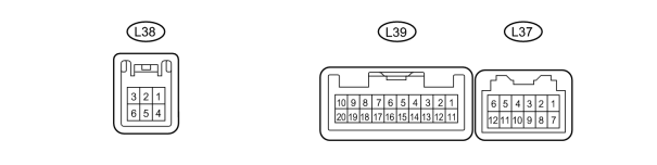
(a) Disconnect the L37 tuner connector.
(b) Measure the resistance and voltage according to the value(s) in the table below.
|
Terminal No. (Symbol) |
Wiring Color |
Terminal Description |
Condition |
Specified Condition |
|---|---|---|---|---|
|
L37-7 (GND) - Body ground |
W-B - Body ground |
Ground |
Always |
Below 1 Ω |
|
L37-11 (ACC) - L37-7 (GND) |
GR - W-B |
ACC power supply |
Engine switch off |
Below 1 V |
|
L37-11 (ACC) - L37-7 (GND) |
GR - W-B |
ACC power supply |
Engine switch on (ACC) |
11 to 14 V |
|
L37-12 (+B) - L37-7 (GND) |
L - W-B |
Battery |
Always |
11 to 14 V |
If the result is not as specified, there may be a malfunction on the wire harness side.
(c) Reconnect the L37 tuner connector.
(d) Measure the voltage according to the value(s) in the table below.
|
Terminal No. (Symbol) |
Wiring Color |
Terminal Description |
Condition |
Specified Condition |
|---|---|---|---|---|
|
L37-1 (SLD) - L37-7 (GND) |
Shielded - W-B |
Shielded |
Always |
Below 1 V |
|
L37-5 (FLO-) - L37-7 (GND) |
R - W-B |
Sound signal (left) |
Engine switch on (ACC), RSE system playing |
Waveform synchronized with sound is output |
|
L37-4 (FLO+) - L37-7 (GND) |
L - W-B |
Sound signal (left) |
Engine switch on (ACC), RSE system playing |
Waveform synchronized with sound is output |
|
L37-2 (FRO+) - L37-7 (GND) |
W - W-B |
Sound signal (right) |
Engine switch on (ACC), RSE system playing |
Waveform synchronized with sound is output |
|
L37-3 (FRO-) - L37-7 (GND) |
B - W-B |
Sound signal (right) |
Engine switch on (ACC), RSE system playing |
Waveform synchronized with sound is output |
|
L37-6 (MUTE) - L37-7 (GND) |
G - W-B |
Mute signal |
Satellite radio on → Changing mode |
3.5 V or higher → Below 1 V |
|
L37-9 (TX+) - L37-7 (GND) |
G - W-B |
AVC-LAN communication signal |
Engine switch on (ACC) |
2 to 3 V |
|
L37-10 (TX-) - L37-7 (GND) |
R - W-B |
AVC-LAN communication signal |
Engine switch on (ACC) |
2 to 3 V |
|
L38-2 (TXO+) - L37-7 (GND) |
B - W-B |
AVC-LAN plus communication signal |
Engine switch on (ACC) |
2 to 3 V |
|
L38-3 (TXI+) - L37-7 (GND) |
B - W-B |
AVC-LAN plus communication signal |
Engine switch on (ACC) |
2 to 3 V |
|
L38-5 (TXO-) - L37-7 (GND) |
W - W-B |
AVC-LAN plus communication signal |
Engine switch on (ACC) |
2 to 3 V |
|
L38-6 (TXI-) - L37-7 (GND) |
W - W-B |
AVC-LAN plus communication signal |
Engine switch on (ACC) |
2 to 3 V |
|
L39-1 (SLD3) - L37-7 (GND) |
Shielded - W-B |
Shielded |
Always |
Below 1 V |
|
L39-2 (RLO-) - L37-7 (GND) |
R - W-B |
Sound signal (left) |
Engine switch on (ACC), RSE system playing |
Waveform synchronized with sound is output |
|
L39-3 (RLO+) - L37-7 (GND) |
L - W-B |
Sound signal (left) |
Engine switch on (ACC), RSE system playing |
Waveform synchronized with sound is output |
|
L39-4 (RRO-) - L37-7 (GND) |
W - W-B |
Sound signal (right) |
Engine switch on (ACC), RSE system playing |
Waveform synchronized with sound is output |
|
L39-5 (RRO+) - L37-7 (GND) |
B - W-B |
Sound signal (right) |
Engine switch on (ACC), RSE system playing |
Waveform synchronized with sound is output |
|
L39-7 (FLI-) - L37-7 (GND) |
R - W-B |
Sound signal (left) |
Engine switch on (ACC), sound library playing |
Waveform synchronized with sound is output |
|
L39-8 (FLI+) - L37-7 (GND) |
G - W-B*1 L - W-B*2 |
Sound signal (left) |
Engine switch on (ACC), sound library playing |
Waveform synchronized with sound is output |
|
L39-9 (FRI-) - L37-7 (GND) |
W - W-B |
Sound signal (right) |
Engine switch on (ACC), sound library playing |
Waveform synchronized with sound is output |
|
L39-10 (FRI+) - L37-7 (GND) |
B - W-B |
Sound signal (right) |
Engine switch on (ACC), sound library playing |
Waveform synchronized with sound is output |
|
L39-13 (MUT4) - L37-7 (GND) |
G - W-B |
Mute signal |
RSE system playing → Changing mode |
3.5 V or higher → Below 1 V |
|
L39-14 (MUT3) - L37-7 (GND) |
G - W-B |
Mute signal |
Audio system playing → Changing mode |
3.5 V or higher → Below 1 V |
|
L39-15 (MUT2) - L37-7 (GND) |
G - W-B |
Mute signal |
Sound library playing → Changing mode |
3.5 V or higher → Below 1 V |
|
L39-17 (RRI+) - L37-7 (GND) |
B - W-B |
Sound signal (right) |
Engine switch on (ACC), audio system playing |
Waveform synchronized with sound is output |
|
L39-18 (RRI-) - L37-7 (GND) |
W - W-B |
Sound signal (right) |
Engine switch on (ACC), audio system playing |
Waveform synchronized with sound is output |
|
L39-19 (RLI+) - L37-7 (GND) |
L - W-B |
Sound signal (left) |
Engine switch on (ACC), audio system playing |
Waveform synchronized with sound is output |
|
L39-20 (RLI-) - L37-7 (GND) |
R - W-B |
Sound signal (left) |
Engine switch on (ACC), audio system playing |
Waveform synchronized with sound is output |
*1: w/ Rear Seat Entertainment System
*2: w/o Rear Seat Entertainment System
If the result is not as specified, the tuner may have a malfunction.
3. CHECK RADIO RECEIVER

4. CHECK STEREO COMPONENT AMPLIFIER

|

|