| Last Modified: 11-27-2007 | 1.6 J | |
| Service Category: Vehicle Interior | Section: Theft Deterrent/Keyless Entry | |
| Model Year: 2008 | Model: LX570 | Doc ID: RM0000027YS00FX |
| Title: THEFT DETERRENT / KEYLESS ENTRY: SMART ACCESS SYSTEM WITH PUSH-BUTTON START (for Start Function): DESCRIPTION (2008 LX570) | ||
|
Power Source Mode does not Change |
DESCRIPTION
When the certification ECU (smart key ECU assembly) has detected the key inside the cabin before the brake pedal is depressed, the power source mode can be changed in the following order sequentially by pressing the engine switch: off → on (ACC) → on (IG) → off.
When one of the DTCs shown in the illustration below is detected, troubleshoot the DTC(s) by following the troubleshooting procedure relevant to the DTC(s). If the power source mode still cannot be changed normally, despite troubleshooting, one of the following may have occurred:
- The LIN communication line is malfunctioning.
- The certification ECU (smart key ECU assembly) has determined that no key is inside the cabin.
- The engine switch is malfunctioning.
- The main body ECU is malfunctioning.
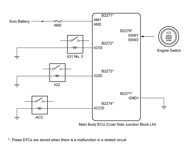
WIRING DIAGRAM
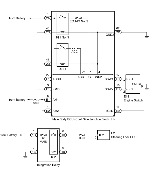
INSPECTION PROCEDURE
HINT:
If the vehicle is in key cancel mode, change to normal mode
 .
.
PROCEDURE
|
1. |
CHECK DTC OUTPUT |
(a) Check whether DTC is output
.
Result
|
Display (DTC output) |
Proceed to |
|---|---|
|
No DTC output |
A |
|
DTC output |
B |
|

|
2. |
CHECK SMART ACCESS SYSTEM WITH PUSH-BUTTON START |
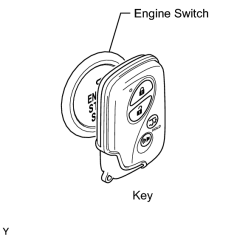
(a) Remove the battery of the electrical key transmitter
.
(b) With the brake pedal depressed, touch the LEXUS mark of the key to the engine switch.
(c) When operating the engine switch, check whether the engine switch changes to on (ACC) or on (IG).
HINT:
- When the electrical key transmitter cannot be verified even when it is in the operational area, the engine start check can be performed by removing the transmitter battery from the electrical key transmitter and holding the transmitter against the engine switch.
- When performing the check, if the engine switch turns on (ACC) or on (IG), there is a problem with key certification inside the cabin.
Result
|
Result |
Proceed to |
|---|---|
|
Does not change to on (ACC) |
A |
|
Does not change to on (IG) |
B |
|
Does not change to on (ACC) and on (IG) |
C |
|
Changes to on (ACC) and on (IG) |
D |
|
|
3. |
INSPECT FUSE (AM2) |
(a) Remove the AM2 fuse from the engine room relay block.
(b) Measure the resistance according to the value(s) in the table below.
Standard Resistance:
|
Tester Connection |
Condition |
Specified Condition |
|---|---|---|
|
AM2 fuse |
Always |
Below 1 Ω |
|
|
4. |
CHECK HARNESS AND CONNECTOR (MAIN BODY ECU - BATTERY AND BODY GROUND) |
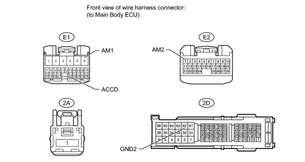
(a) Disconnect the E1, E2, 2A and 2D main body ECU connectors.
(b) Measure the voltage and resistance according to the value(s) in the table below.
Standard Voltage:
|
Tester Connection |
Condition |
Specified Condition |
|---|---|---|
|
E1-6 (AM1) - Body ground |
Always |
11 to 14 V |
|
E2-1 (AM2) - Body ground |
Always |
11 to 14 V |
|
2A-1 - Body ground |
Always |
11 to 14 V |
Standard Resistance:
|
Tester Connection |
Condition |
Specified Condition |
|---|---|---|
|
E1-22 (ACCD) - 2D-45 |
Always |
Below 1 Ω |
|
2D-62 (GND2) - Body ground |
Always |
Below 1 Ω |
|
E1-22 (ACCD) or 2D-45 - Body ground |
Always |
10 kΩ or higher |
|
|
6. |
INSPECT FUSE (AM2) |
(a) Remove the AM2 fuse from the engine room relay block.
(b) Measure the resistance according to the value(s) in the table below.
Standard Resistance:
|
Tester Connection |
Condition |
Specified Condition |
|---|---|---|
|
AM2 fuse |
Always |
Below 1 Ω |
|
|
7. |
CHECK HARNESS AND CONNECTOR (MAIN BODY ECU - BATTERY AND BODY GROUND) |
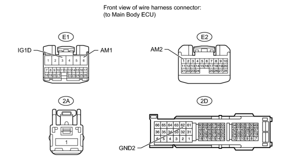
(a) Disconnect the E1, E2, 2A and 2D main body ECU connectors.
(b) Measure the voltage and resistance according to the value(s) in the table below.
Standard Voltage:
|
Tester Connection |
Condition |
Specified Condition |
|---|---|---|
|
E1-6 (AM1) - Body ground |
Always |
11 to 14 V |
|
E2-1 (AM2) - Body ground |
Always |
11 to 14 V |
|
2A-1 - Body ground |
Always |
11 to 14 V |
Standard Resistance:
|
Tester Connection |
Condition |
Specified Condition |
|---|---|---|
|
E1-3 (IG1D) - 2D-43 |
Always |
Below 1 Ω |
|
2D-62 (GND2) - Body ground |
Always |
Below 1 Ω |
|
E1-3 (IG1D) or 2D-43 - Body ground |
Always |
10 kΩ or higher |
|
|
8. |
INSPECT INTEGRATION RELAY (IG2 RELAY) |
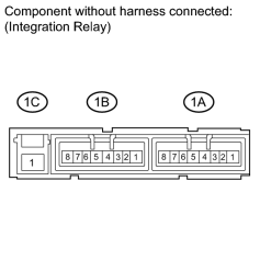
(a) Remove the integration relay from the engine room relay block.
(b) Measure the resistance according to the value(s) in the table below.
Standard Resistance:
|
Tester Connection |
Condition |
Specified Condition |
|---|---|---|
|
1B-8 - 1C-1 |
Battery voltage applied to terminals 1B-6 and 1B-7 |
Below 1 Ω |
|
1B-8 - 1C-1 |
Battery voltage not applied to terminals 1B-6 and 1B-7 |
10 kΩ or higher |
|
|
9. |
CHECK HARNESS AND CONNECTOR (INTEGRATION RELAY (IG2 RELAY) - MAIN BODY ECU AND BODY GROUND) |
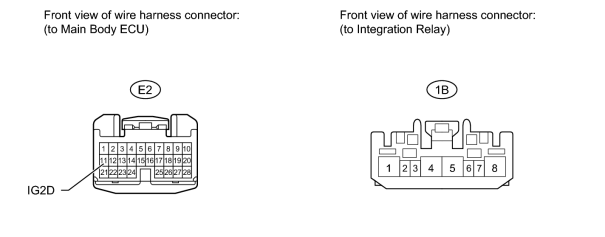
(a) Disconnect the E2 main body ECU connector.
(b) Disconnect the 1B integration relay connector.
(c) Measure the resistance according to the value(s) in the table below.
Standard Resistance:
|
Tester Connection |
Condition |
Specified Condition |
|---|---|---|
|
E2-11 (IG2D) - 1B-6 |
Always |
Below 1 Ω |
|
1B-7 - Body ground |
Always |
Below 1 Ω |
|
E2-11 (IG2D) or 1B-6 - Body ground |
Always |
10 kΩ or higher |
|
|
10. |
INSPECT FUSE (IGN, IG2 MAIN) |
(a) Remove the IGN and IG2 MAIN fuses from the engine room relay block.
(b) Measure the resistance according to the value(s) in the table below.
Standard Resistance:
|
Tester Connection |
Condition |
Specified Condition |
|---|---|---|
|
IGN fuse |
Always |
Below 1 Ω |
|
IG2 MAIN fuse |
Always |
Below 1 Ω |
|
|
11. |
CHECK HARNESS AND CONNECTOR (INTEGRATION RELAY (IG2 RELAY) - STEERING LOCK ECU AND BATTERY) |
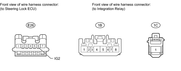
(a) Disconnect the E26 steering lock ECU connector.
(b) Disconnect the 1B and 1C integration relay connectors.
(c) Measure the voltage and resistance according to the value(s) in the table below.
Standard Voltage:
|
Tester Connection |
Condition |
Specified Condition |
|---|---|---|
|
1C-1 - Body ground |
Always |
11 to 14 V |
Standard Resistance:
|
Tester Connection |
Condition |
Specified Condition |
|---|---|---|
|
E26-6 (IG2) - 1B-8 |
Always |
Below 1 Ω |
|
E26-6 (IG2) or 1B-8 - Body ground |
Always |
10 kΩ or higher |
|
|
13. |
INSPECT FUSE (AM2) |
(a) Remove the AM2 fuse from the engine room relay block.
(b) Measure the resistance according to the value(s) in the table below.
Standard Resistance:
|
Tester Connection |
Condition |
Specified Condition |
|---|---|---|
|
AM2 fuse |
Always |
Below 1 Ω |
|
|
14. |
CHECK HARNESS AND CONNECTOR (MAIN BODY ECU - BATTERY AND BODY GROUND) |
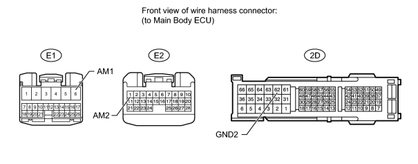
(a) Disconnect the E1, E2 and 2D main body ECU connectors.
(b) Measure the voltage and resistance according to the value(s) in the table below.
Standard Voltage:
|
Tester Connection |
Condition |
Specified Condition |
|---|---|---|
|
E1-6 (AM1) - Body ground |
Always |
11 to 14 V |
|
E2-1 (AM2) - Body ground |
Always |
11 to 14 V |
Standard Resistance:
|
Tester Connection |
Condition |
Specified Condition |
|---|---|---|
|
2D-62 (GND2) - Body ground |
Always |
Below 1 Ω |
|
|
15. |
INSPECT ENGINE SWITCH |
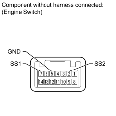
(a) Disconnect the E18 engine switch connector.
(b) Measure the resistance according to the value(s) in the table below.
Standard Resistance:
|
Tester Connection |
Switch Condition |
Specified Condition |
|---|---|---|
|
7 (SS1) - 5 (GND) |
Pushed |
Below 1 Ω |
|
2 (SS2) - 5 (GND) |
Pushed |
Below 1 Ω |
|
7 (SS1) - 5 (GND) |
Not pushed |
10 kΩ or higher |
|
2 (SS2) - 5 (GND) |
Not pushed |
10 kΩ or higher |
|
|
16. |
CHECK HARNESS AND CONNECTOR (ENGINE SWITCH - MAIN BODY ECU AND BODY GROUND) |
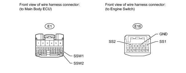
(a) Disconnect the E1 main body ECU connector.
(b) Disconnect the E18 engine switch connector.
(c) Measure the resistance according to the value(s) in the table below.
Standard Resistance:
|
Tester Connection |
Condition |
Specified Condition |
|---|---|---|
|
E1-17 (SSW1) - E18-7 (SS1) |
Always |
Below 1 Ω |
|
E1-16 (SSW2) - E18-2 (SS2) |
Always |
Below 1 Ω |
|
E18-5 (GND) - Body ground |
Always |
Below 1 Ω |
|
E1-17 (SSW1) or E18-7 (SS1) - Body ground |
Always |
10 kΩ or higher |
|
E1-16 (SSW2) or E18-2 (SS2) - Body ground |
Always |
10 kΩ or higher |
|

|

|