| Last Modified: 11-27-2007 | 1.6 A | |
| Service Category: Suspension | Section: Front Suspension | |
| Model Year: 2008 | Model: LX570 | Doc ID: RM000002C8I00DX |
| Title: FRONT SUSPENSION: FRONT UPPER SUSPENSION ARM: INSTALLATION (2008 LX570) | ||
INSTALLATION
HINT:
- Use the same procedures for the RH side and LH side.
- The procedures listed below are for the LH side.
-
A bolt without a torque specification is shown in the standard bolt chart
 .
.
1. TEMPORARILY INSTALL FRONT SUSPENSION UPPER ARM ASSEMBLY LH
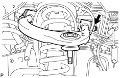
(a) Temporarily install the suspension upper arm with the 2 washers, bolt and nut.
HINT:
After stabilizing the suspension, tighten the nut.
2. CONNECT STEERING KNUCKLE LH
(a) Connect the steering knuckle to the suspension upper arm.
(b) Install the nut and a new cotter pin.
Torque: 110 N·m (1122 kgf·cm, 81 ft·lbf)
NOTICE:
If the holes for the cotter pin are not aligned, tighten the nut further up to 60°.
3. CONNECT SKID CONTROL SENSOR WIRE
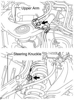
(a) Connect the sensor wire to the steering knuckle and upper arm with the bolt and nut.
Torque: 13 N·m (133 kgf·cm, 9.6 ft·lbf)
4. STABILIZE SUSPENSION
5. TIGHTEN FRONT SUSPENSION UPPER ARM ASSEMBLY LH
(a) Tighten the nut.
Torque: 185 N·m (1886 kgf·cm, 136 ft·lbf)
NOTICE:
Perform this procedure with all 4 wheels on the ground.
6. INSTALL FRONT HEIGHT CONTROL SENSOR SUB-ASSEMBLY LH
7. INSTALL FRONT FENDER APRON SEAL REAR LH
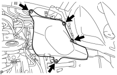
|
(a) Install the apron seal with the 4 clips. |
8. INSTALL FRONT FENDER APRON SEAL LH
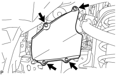
|
(a) Install the apron seal with the 4 clips. |
9. CONNECT CABLE TO NEGATIVE BATTERY TERMINAL
NOTICE:
When disconnecting the cable, some systems need to be initialized after the cable is reconnected
.
10. PERFORM VEHICLE HEIGHT OFFSET CALIBRATION
(a) Perform the vehicle height offset calibration
.
11. ADJUST FRONT HEIGHT CONTROL SENSOR SUB-ASSEMBLY LH
12. PERFORM ZERO POINT CALIBRATION OF G SENSOR
(a) Perform the zero point calibration of G sensor
.
13. ADJUST HEADLIGHT ASSEMBLY
(a) Adjust the headlight assembly
.

|

|