| Last Modified: 11-27-2007 | 1.6 A | |
| Service Category: Drivetrain | Section: Transfer/4wd/Awd | |
| Model Year: 2008 | Model: LX570 | Doc ID: RM000002HO8007X |
| Title: JF2A TRANSFER / 4WD / AWD: TRANSFER ASSEMBLY: DISASSEMBLY (2008 LX570) | ||
DISASSEMBLY
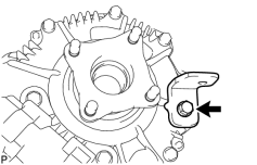
1. REMOVE PROPELLER SHAFT HEAT INSULATOR BRACKET SUB-ASSEMBLY
|
(a) Remove the bolt and bracket. |
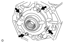
2. REMOVE TRANSFER OIL PUMP PLATE
|
(a) Remove the 4 bolts, oil pump plate and oil pump driven rotor. NOTICE:
Do not drop the oil pump driven rotor. |
(b) Remove the O-ring from the oil pump plate.
|
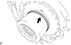
(c) Remove the transfer oil seal ring from the input shaft. |
|
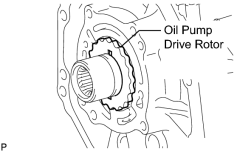
(d) Remove the oil pump drive rotor from the input shaft. |
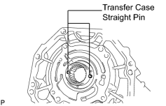
3. REMOVE TRANSFER CASE STRAIGHT PIN
|
(a) Remove the 2 straight pins. NOTICE:
Do not drop the straight pins. |
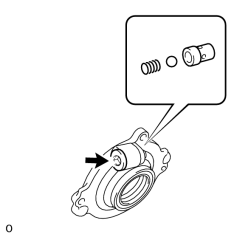
4. REMOVE TRANSFER CASE PLUG
|
(a) Using a 10 mm hexagon wrench, remove the case plug, compression spring, ball and relief valve seat. |
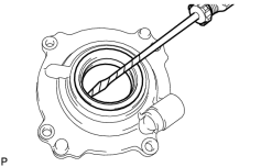
5. REMOVE TRANSFER OIL PUMP PLATE OIL SEAL
|
(a) Using a screwdriver, pry out the oil seal from the oil pump plate. NOTICE:
Be careful not to damage the oil seal and oil pump plate contact surfaces. HINT:
Tape the screwdriver tip before use. |
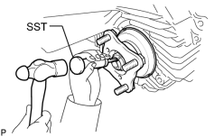
6. REMOVE FRONT OUTPUT SHAFT COMPANION FLANGE SUB-ASSEMBLY
|
(a) Using SST and a hammer, release the staked part of the nut. SST: 09930-00010 09931-00010 09931-00020 NOTICE:
|
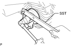
|
(b) Using SST to hold the companion flange, remove the lock nut. SST: 09330-00021 |
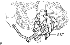
|
(c) Using SST, remove the companion flange. SST: 09950-40011 09951-04020 09952-04010 09953-04030 09954-04010 09955-04051 09957-04010 09958-04011 |
(d) Remove the O-ring from the companion flange.
7. REMOVE TRANSFER CASE FRONT OIL SEAL

8. REMOVE REAR OUTPUT SHAFT COMPANION FLANGE SUB-ASSEMBLY
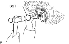
|
(a) Using SST and a hammer, release the staked part of the nut. SST: 09930-00010 09931-00010 09931-00020 NOTICE:
|
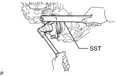
|
(b) Using SST to hold the companion flange, remove the lock nut. SST: 09330-00021 |
|
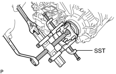
(c) Using SST, remove the companion flange. SST: 09950-40011 09951-04020 09952-04010 09953-04030 09954-04010 09955-04051 09957-04010 09958-04011 |
(d) Remove the O-ring from the companion flange.
9. REMOVE TRANSFER CASE REAR OIL SEAL
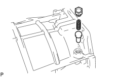
10. REMOVE NO. 1 TRANSFER CASE PLUG
|
(a) Remove the plug, compression spring and pin. |
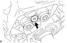
11. REMOVE TRANSFER CASE PLUG
|
(a) Using a 6 mm hexagon wrench, remove the plug. |
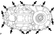
12. REMOVE REAR TRANSFER CASE ASSEMBLY
|
(a) Remove the 14 bolts. |
(b) Remove the rear transfer case.
HINT:
If necessary, tap the rear transfer case with a plastic-faced hammer to remove it.
13. REMOVE FRONT TRANSFER OUTPUT SHAFT NEEDLE ROLLER BEARING
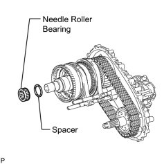
(a) Remove the needle roller bearing and spacer from the output shaft.
14. REMOVE NO. 2 TRANSFER GEAR SHIFT FORK
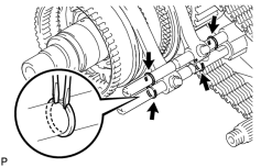
|
(a) Using 2 screwdrivers and a hammer, tap off the 4 shift fork shaft snap rings. |
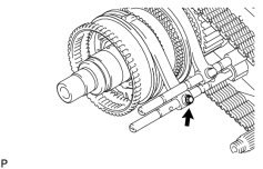
|
(b) Remove the bolt. Then remove the No. 2 gear shift fork together with the high and low clutch sleeve from the shift actuator. |
15. REMOVE TRANSFER SHIFT ACTUATOR ASSEMBLY
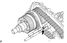
|
(a) Remove the No. 1 gear shift fork bolt. |
|
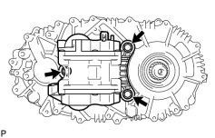
(b) Remove the 3 bolts. |
|
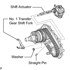
(c) Remove the shift actuator, No. 1 gear shift fork, washer, and straight pin from the rear transfer case. NOTICE:
Take care not to drop the No. 1 gear shift fork, washer, and straight pin. |
|
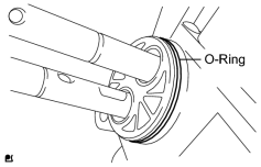
(d) Remove the O-ring from the shift actuator. |
16. REMOVE REAR TRANSFER OUTPUT SHAFT ASSEMBLY
|
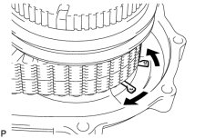
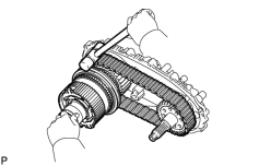
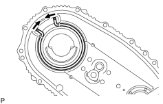
(a) Using a snap ring expander, expand the snap ring as shown in the illustration. |
|
(b) Using a plastic-faced hammer, carefully tap the rear transfer case, and remove the output shaft together with the drive chain and driven sprocket. |
(c) Remove the output shaft and driven sprocket from the drive chain.
NOTICE:
Do not drop the output shaft washers.
|
(d) Using a snap ring expander, remove the snap ring from the rear transfer case. |
17. REMOVE FRONT DRIVE CLUTCH SLEEVE
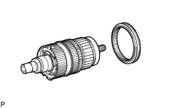
(a) Remove the clutch sleeve from the output shaft.
18. REMOVE SIDE GEAR SHAFT HOLDER BEARING
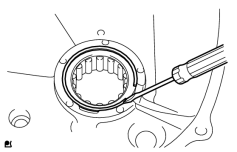
|
(a) Using a screwdriver, remove the snap ring. |
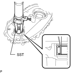
|
(b) Using SST, remove the bearing. SST: 09308-00010 |
19. REMOVE TRANSFER OIL SEPARATOR SUB-ASSEMBLY
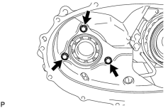
|
(a) Remove the 3 bolts and oil separator. |
(b) Remove the O-ring from the oil separator.
20. REMOVE TRANSFER CASE MAGNET
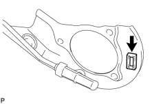
(a) Remove the magnet from the oil separator.
21. REMOVE TRANSFER INPUT SHAFT ASSEMBLY
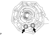
|
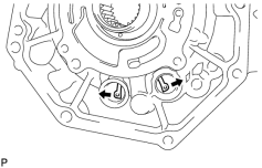
(a) Using a 14 mm hexagon wrench, remove the 2 case plugs from the front transfer case. |
|
(b) Using a snap ring expander, expand the snap ring as shown in the illustration. Then remove the input shaft from the front transfer case. |
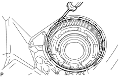
22. REMOVE TRANSFER LOW PLANETARY RING GEAR
|
(a) Using a screwdriver, remove the snap ring. Then remove the low planetary ring gear from the front transfer case. |
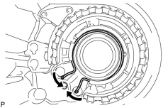
|
(b) Using a snap ring expander, remove the snap ring from the front transfer case. |
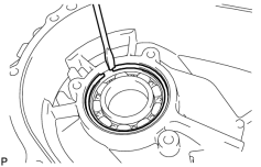
23. REMOVE TRANSFER DRIVEN SPROCKET BEARING
|
(a) Using a screwdriver, remove the snap ring. Then remove the bearing from the front transfer case. |
24. REMOVE NO. 1 SYNCHRONIZER RING
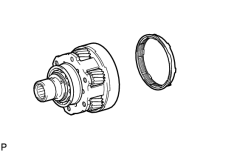
(a) Remove the synchronizer ring from the input shaft.
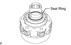
25. REMOVE NO. 1 TRANSFER INPUT SHAFT SEAL RING
|
(a) Remove the seal ring from the input shaft. |
26. REMOVE TRANSFER INPUT SHAFT BEARING
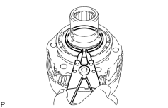
|
(a) Using a snap ring expander, remove the snap ring. |
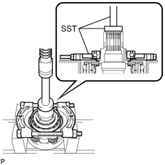
|
(b) Using SST and a press, press out the bearing. SST: 09555-55010 SST: 09950-60010 09951-00490 SST: 09950-70010 09951-07100 NOTICE:
Be careful not to drop or damage the input shaft, low planetary gear and low planetary gear bearings. HINT:
When the bearing is removed, the input shaft, low planetary gear, and 2 low planetary gear bearings will come off. |
27. REMOVE TRANSFER INPUT SHAFT BIMETAL FORMED BUSH
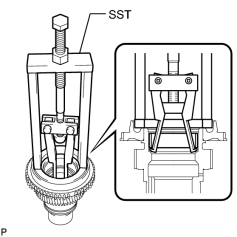
|
(a) Using SST, remove the bush. SST: 09387-00041 09387-01021 09387-01030 09387-01040 |
28. REMOVE TRANSFER INPUT SHAFT PLUG
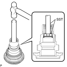
|
(a) Using SST and a hammer, tap out the input shaft plug. SST: 09950-70010 09951-07150 SST: 09950-60010 09951-00300 |
29. REMOVE TRANSFER OUTPUT SHAFT WASHER
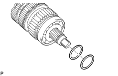
|
(a) Remove the 2 output shaft washers from the output shaft. |
30. REMOVE NO. 1 TRANSFER OUTPUT SHAFT SPACER
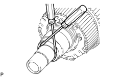
|
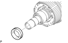
(a) Using 2 screwdrivers and a hammer, tap off the snap ring. |
|
(b) Remove the output shaft spacer from the output shaft. |
|
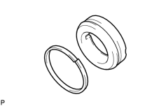
(c) Remove the seal ring from the output shaft spacer. |
|
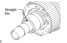
(d) Remove the straight pin from the output shaft. |
31. REMOVE CENTER DIFFERENTIAL CASE
|
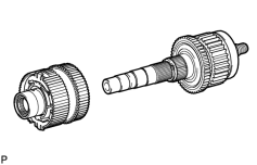
(a) Remove the center differential case from the output shaft. |
|
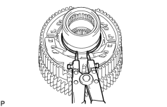
(b) Using a snap ring expander, remove the snap ring. |
|
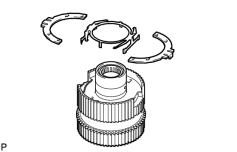
(c) Remove the synchromesh shifting key spring and No. 2 synchromesh shifting keys from the center differential case. |
|
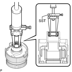
(d) Using SST, remove the needle roller bearing. SST: 09308-00010 |
|
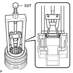
(e) Using SST, remove the needle roller bearing. SST: 09387-00041 09387-01021 09387-01030 09387-01040 |
32. REMOVE TRANSFER OUTPUT SHAFT SPACER
|
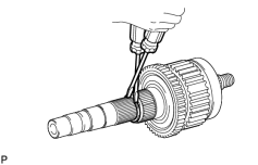
(a) Using 2 screwdrivers and a hammer, tap off the snap ring. |
|
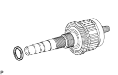
(b) Remove the output shaft spacer from the output shaft. |
|
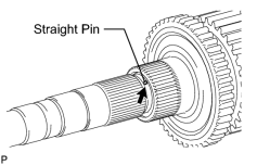
(c) Remove the straight pin from the output shaft. |
33. REMOVE TRANSFER DRIVE SPROCKET SUB-ASSEMBLY
|
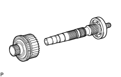
(a) Remove the drive sprocket from the output shaft. |
34. REMOVE TRANSFER DRIVE SPROCKET BEARING
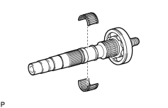
|
(a) Remove the bearing from the output shaft. |
35. REMOVE REAR TRANSFER OUTPUT SHAFT
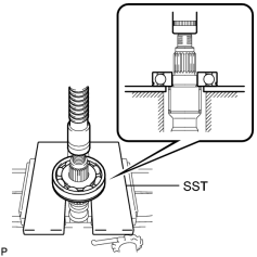
|
(a) Using SST and a press, press out the bearing. SST: 09527-10011 NOTICE:
Be careful not to drop or damage the output shaft. |
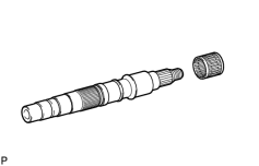
|
(b) Remove the needle roller bearing from the output shaft. |

|

|