| Last Modified: 11-27-2007 | 1.6 J | |
| Service Category: Vehicle Exterior | Section: Window/Glass | |
| Model Year: 2008 | Model: LX570 | Doc ID: RM000002LI800FX |
| Title: WINDOW / GLASS: WINDOW DEFOGGER SYSTEM: DESCRIPTION (2008 LX570) | ||
|
Rear Window Defogger System does not Operate |
DESCRIPTION
When the rear window defogger switch is turned on, a rear window defogger activation request signal is sent via the CAN communication line to the air conditioning amplifier. Then the air conditioning amplifier operates the rear window defogger. When the on signal from the switch is received, the defogger relay (DEFOG) is operated for 15 minutes. Also, if the off signal from the switch is received within 15 minutes, the defogger relay (DEFOG) operation is stopped.
WIRING DIAGRAM
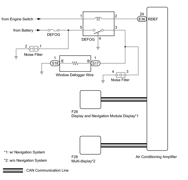
INSPECTION PROCEDURE
PROCEDURE
|
1. |
CHECK FOR DTC |
(a) Check for DTC.
OK:
DTC is not output.
|

|
2. |
PERFORM ACTIVE TEST USING TECHSTREAM (DEFOGGER RELAY) |
(a) Select the Active Test using the Techstream to generate a control command, and then check that the rear window defogger operates.
Air Conditioner
|
Tester Display |
Test Part |
Control Range |
Diagnostic Note |
|---|---|---|---|
|
Defogger Relay (Rear) |
Rear window defogger relay operation |
OFF or ON |
- |
Result
|
Result |
Proceed to |
|---|---|
|
Rear window defogger operates normally (w/ Navigation System) |
A |
|
Rear window defogger operates normally (w/o Navigation System) |
B |
|
Rear window defogger does not operate |
C |
|
|
3. |
REPLACE DISPLAY AND NAVIGATION MODULE DISPLAY |
(a) Temporarily replace the display and navigation module display with a new or normally functioning one
 .
.
|
|
4. |
CHECK WINDOW DEFOGGER SYSTEM |
(a) Turn the engine switch on (IG).
(b) Check that pressing the defogger switch illuminates the indicator and warms the rear window surface.
(c) Check that after approximately 15 minutes, the indicator light turns off and the rear window defogger deactivates.
OK:
Rear window defogger system functioning normally.
|
|
5. |
REPLACE MULTI-DISPLAY |
(a) Temporarily replace the multi-display with a new or normally functioning one
.
|
|
6. |
CHECK WINDOW DEFOGGER SYSTEM |
(a) Turn the engine switch on (IG).
(b) Check that pressing the defogger switch illuminates the indicator and warms the rear window surface.
(c) Check that after approximately 15 minutes, the indicator light turns off and the rear window defogger deactivates.
OK:
Rear window defogger system functioning normally.
|
|
7. |
CHECK FUSE (DEFOG) |
(a) Remove the DEFOG H-fuse from the engine room relay block.
(b) Measure the resistance according to the value(s) in the table below.
Standard Resistance:
|
Tester Connection |
Condition |
Specified Condition |
|---|---|---|
|
DEFOG H-fuse |
Always |
Below 1 Ω |
|
|
8. |
INSPECT DEFOGGER RELAY (DEFOG) |
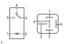
(a) Remove the defogger relay from the engine room relay block.
(b) Measure the resistance according to the value(s) in the table below.
Standard Resistance:
|
Tester Connection |
Condition |
Specified Condition |
|---|---|---|
|
3 - 4 |
Battery voltage is not applied to terminals 1 and 2 |
Below 1 Ω |
|
3 - 5 |
10 kΩ or higher |
|
|
3 - 4 |
Battery voltage is applied to terminals 1 and 2 |
10 kΩ or higher |
|
3 - 5 |
Below 1 Ω |
|
|
9. |
CHECK HARNESS AND CONNECTOR (DEFOGGER RELAY - BATTERY AND AIR CONDITIONING AMPLIFIER) |
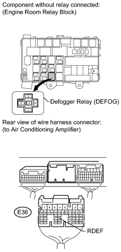
(a) Remove the defogger relay from the engine room relay block.
(b) Disconnect the E36 air conditioning amplifier connector.
(c) Measure the voltage according to the value(s) in the table below.
Standard Voltage:
|
Tester Connection |
Condition |
Specified Condition |
|---|---|---|
|
Defogger relay terminal 1 - Body ground |
Engine switch on (IG) |
11 to 14 V |
|
Defogger relay terminal 5 - Body ground |
Always |
11 to 14 V |
(d) Measure the resistance according to the value(s) in the table below.
Standard Resistance:
|
Tester Connection |
Condition |
Specified Condition |
|---|---|---|
|
Defogger relay terminal 2 - E36-24 (RDEF) |
Always |
Below 1 Ω |
|
Defogger relay terminal 2 - Body ground |
Always |
10 kΩ higher |
|
|
10. |
CHECK HARNESS AND CONNECTOR (WINDOW DEFOGGER WIRE - DEFOGGER RELAY AND BODY GROUND) |
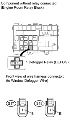
(a) Disconnect the S17 and S18 defogger connectors.
(b) Remove the defogger relay from the engine room relay block.
(c) Measure the resistance according to the value(s) in the table below.
Standard Resistance:
|
Tester Connection |
Condition |
Specified Condition |
|---|---|---|
|
S17-1 (B) - Defogger relay terminal 3 |
Always |
Below 1 Ω |
|
S18-1 (E) - Body ground |
||
|
Defogger relay terminal 4 - Body ground |
||
|
S17-1 (B) - Body ground |
Always |
10 kΩ or higher |
|
|
11. |
CHECK REAR WINDOW DEFOGGER WIRE |
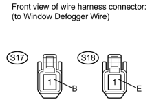
(a) Disconnect the S17 and S18 defogger connector.
(b) Measure the voltage according to the value(s) in the table below.
Standard Voltage:
|
Tester Connection |
Condition |
Specified Condition |
|---|---|---|
|
S17-1 (B) - S18-1 (E) |
Engine switch on (IG) and defogger switch on |
11 to 14 V |
|

|

|