| Last Modified: 11-27-2007 | 1.6 J | |
| Service Category: Vehicle Exterior | Section: Lighting (ext) | |
| Model Year: 2008 | Model: LX570 | Doc ID: RM000002ZP2006X |
| Title: LIGHTING (EXT): LIGHTING SYSTEM: DESCRIPTION (2008 LX570) | ||
|
Turn Signal Light does not Illuminate |
DESCRIPTION
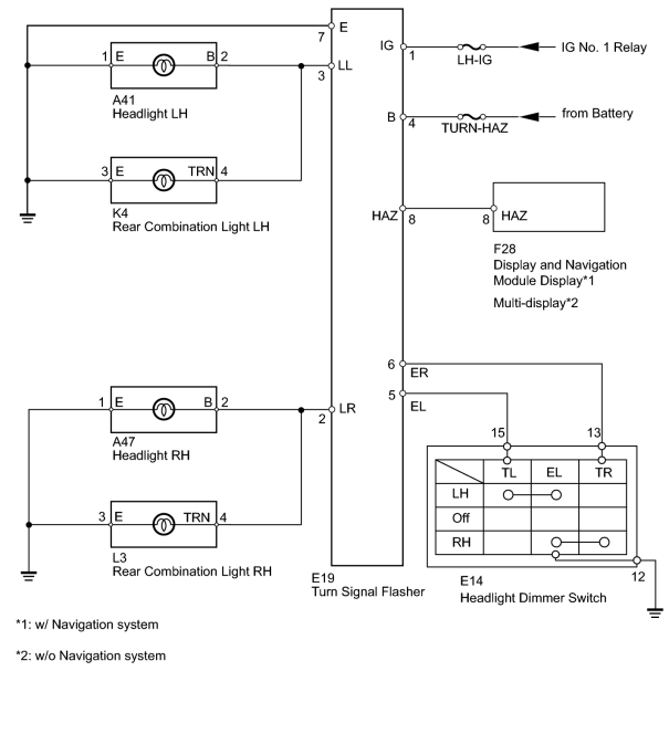
The turn signal flasher receives a turn signal switch signal from the headlight dimmer switch, and illuminates the front turn signal light and rear combination light.
WIRING DIAGRAM
INSPECTION PROCEDURE
PROCEDURE
|
1. |
CHECK SWITCH FUNCTION |
(a) Check if the hazard warning switch and headlight dimmer switch operate normally. Hazard warning switch and headlight dimmer switch do not operate
Result
|
Result |
Proceed to |
|---|---|
|
Hazard warning switch and Headlight dimmer |
A |
|
Only hazard warning switch does not operate |
B |
|
Only headlight dimmer switch does not operate (w/ Navigation) |
C |
|
Only headlight dimmer switch does not operate (w/o Navigation) |
D |
|

|
2. |
CHECK HARNESS AND CONNECTOR (TURN SIGNAL FLASHER - BATTERY) |
(a) Disconnect the turn signal flasher connector.
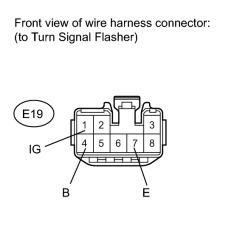
(b) Measure the resistance and voltage according to the value(s) in the table below.
Standard Resistance:
|
Tester Connection |
Condition |
Specified Condition |
|---|---|---|
|
E19-7 (E) - Body ground |
Always |
Below 1 Ω |
Standard Voltage:
|
Tester Connection |
Switch Condition |
Specified Condition |
|---|---|---|
|
E19-1 (IG) - Body ground |
Engine switch on (IG) |
11 to 14 V |
|
E19-4 (B) - Body ground |
Always |
11 to 14 V |
|
|
3. |
CHECK TURN SIGNAL LIGHT FUNCTION |
(a) Check the malfunctioning turn signal light.
Result
|
Result |
Proceed to |
|---|---|
|
LH |
A |
|
RH |
B |
|
|
4. |
CHECK HARNESS AND CONNECTOR (REAR COMBINATION LIGHT - TURN SIGNAL FLASHER AND BODY GROUND) |
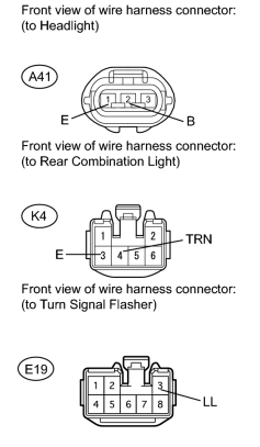
(a) Disconnect the E19 turn signal flasher connector.
(b) Disconnect the A41 and K4 light connectors.
(c) Measure the resistance according to the value(s) in the table below.
Standard Resistance:
|
Tester Connection |
Condition |
Specified Condition |
|---|---|---|
|
A41-2 (B) - E19-3 (LL) |
Always |
Below 1 Ω |
|
A41-1 (E) - Body ground |
||
|
K4-4 (TRN) - E19-3 (LL) |
||
|
K4-3 (E) - Body ground |
||
|
K4-4 (TRN) - Body ground |
Always |
10 kΩ or higher |
|
A41-2 (B) - Body ground |
Result
|
Result |
Proceed to |
|---|---|
|
OK (Headlight does not flash) |
A |
|
OK (Rear combination light does not flash) |
B |
|
NG |
C |
|
|
5. |
CHECK HARNESS AND CONNECTOR (FRONT TURN SIGNAL LIGHT - TURN SIGNAL FLASHER AND BODY GROUND) |
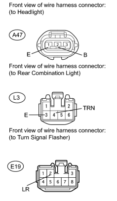
(a) Disconnect the E19 turn signal flasher connector.
(b) Disconnect the A47 and L3 light connectors.
(c) Measure the resistance according to the value(s) in the table below.
Standard Resistance:
|
Tester Connection |
Condition |
Specified Condition |
|---|---|---|
|
A47-2 (B) - E19-2 (LR) |
Always |
Below 1 Ω |
|
A47-1 (E) - Body ground |
||
|
L3-4 (TRN) - E19-2 (LR) |
||
|
L3-3 (E) - Body ground |
||
|
L3-4 (TRN) - Body ground |
Always |
10 kΩ or higher |
|
A47-2 (B) - Body ground |
Result
|
Result |
Proceed to |
|---|---|
|
OK (Headlight does not flash) |
A |
|
OK (Rear combination light does not flash) |
B |
|
NG |
C |
|
|
6. |
INSPECT HEADLIGHT DIMMER SWITCH (TURN SIGNAL SWITCH) |
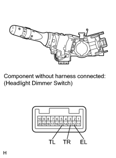
|
(a) Remove the headlight dimmer switch
|
(b) Measure the resistance according to the value(s) in the table below.
Standard Resistance:
|
Tester Connection |
Switch Condition |
Specified Condition |
|---|---|---|
|
13 (TR) - 12 (EL) |
Turn signal switch right turn |
Below 1 Ω |
|
Turn signal switch off |
10 kΩ or higher |
|
|
15 (TL) - 12 (EL) |
Turn signal switch left turn |
Below 1 Ω |
|
Turn signal switch off |
10 kΩ or higher |
|
|
7. |
CHECK HARNESS AND CONNECTOR (HEADLIGHT DIMMER SWITCH - TURN SIGNAL FLASHER AND BODY GROUND) |
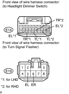
|
(a) Disconnect the E14 switch connector. |
(b) Disconnect the E19 turn signal flasher connector.
(c) Measure the resistance according to the value(s) in the table below.
Standard Resistance:
|
Tester Connection |
Condition |
Specified Condition |
|---|---|---|
|
E14-13 (TR) - E19-6 (ER) |
Always |
Below 1 Ω |
|
E14-15 (TL) - E19-5 (TL) |
||
|
E14-12 (EL) - Body ground |
||
|
E14-13 (TR) - Body ground |
Always |
10 kΩ or higher |
|
E14-15 (TL) - Body ground |
|
|
8. |
CHECK HARNESS AND CONNECTOR (TURN SIGNAL FLASHER - DISPLAY AND NAVIGATION MODULE DISPLAY) |

(a) Disconnect the E19 turn signal flasher connector.
(b) Disconnect the F28 display and navigation module display connector.
(c) Measure the resistance according to the value(s) in the table below.
Standard Resistance:
|
Tester Connection |
Condition |
Specified Condition |
|---|---|---|
|
F28-8 (HAZ) - E19-8 (HAZ) |
Always |
Below 1 Ω |
|
F28-8 (HAZ) - body ground |
Always |
10 kΩ or higher |
|
|
9. |
CHECK DISPLAY AND NAVIGATION MODULE DISPLAY (HAZARD WARNING SWITCH) |
(a) Temporarily replace the display and navigation module display with a new or normally functioning one
 .
.
(b) Check the hazard warning switch operation.
OK:
Hazard warning switch operation is normal.
|
|
10. |
CHECK HARNESS AND CONNECTOR (TURN SIGNAL FLASHER - MULTI-DISPLAY) |
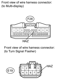
(a) Disconnect the E19 turn signal flasher connector.
(b) Disconnect the F28 multi-display connector.
(c) Measure the resistance according to the value(s) in the table below.
Standard Resistance:
|
Tester Connection |
Condition |
Specified Condition |
|---|---|---|
|
F28-8 (HAZ) - E19-8 (HAZ) |
Always |
Below 1 Ω |
|
F28-8 (HAZ) - body ground |
Always |
10 kΩ or higher |
|
|
11. |
CHECK MULTI-DISPLAY (HAZARD WARNING SWITCH) |
(a) Temporarily replace the multi-display with a new or normally functioning one
.
(b) Check the hazard warning switch operation.
OK:
Hazard warning switch operation is normal.
|

|

|