| Last Modified: 11-27-2007 | 1.6 A | |
| Service Category: Engine/Hybrid System | Section: Emission Control | |
| Model Year: 2008 | Model: LX570 | Doc ID: RM0000030WE006X |
| Title: 3UR-FE EMISSION CONTROL: AIR SWITCHING VALVE: INSTALLATION (2008 LX570) | ||
INSTALLATION
1. INSTALL NO. 3 AIR TUBE
|
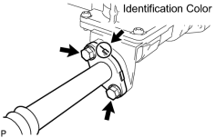
(a) Install a new gasket and the No. 3 air tube with the 2 bolts. Torque: 10 N·m (102 kgf·cm, 7 ft·lbf) HINT:
The identification color on the flange is orange. NOTICE:
Make sure the claws on the gasket are not caught between the air tube and air switching valve. |
2. INSTALL NO. 2 AIR TUBE
|
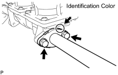
(a) Install a new gasket and the No. 2 air tube with the 2 bolts. Torque: 10 N·m (102 kgf·cm, 7 ft·lbf) HINT:
The identification color on the flange is blue. NOTICE:
Make sure the claws on the gasket are not caught between the air tube and air switching valve. |
3. INSTALL AIR SWITCHING VALVE ASSEMBLY
|
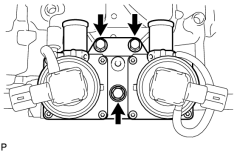
(a) Install the air switching valve with the 3 bolts. Torque: 21 N·m (214 kgf·cm, 15 ft·lbf) |
(b) Connect the 2 air switching valve connectors.
|
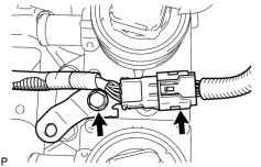
(c) Install the bracket with the bolt. Torque: 8.0 N·m (82 kgf·cm, 71 in·lbf) |
(d) Connect the knock sensor connector.
4. INSTALL AIR PIPE SUB-ASSEMBLY
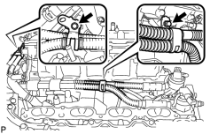
(a) Connect the 2 No. 1 air hoses to the air pipe.
|
(b) Connect the air pipe to the air switching valve, and install the air pipe with the 2 bolts. Torque: 10 N·m (102 kgf·cm, 7 ft·lbf) |
|
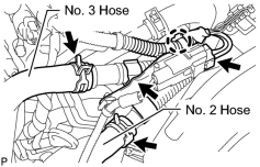
(c) Connect the air pump connector clamp holder. |
(d) Attach the wire harness claw.
(e) Connect the air pump connector.
(f) Connect the No. 2 and No. 3 hoses.
5. INSTALL FRONT WATER BY-PASS JOINT
|
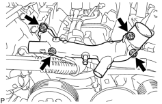
(a) Install 2 new gaskets and the front water by-pass joint with the 4 nuts. Torque: 21 N·m (214 kgf·cm, 15 ft·lbf) |
(b) Connect the engine coolant temperature sensor connector.
6. CONNECT NO. 2 WATER BY-PASS PIPE SUB-ASSEMBLY (w/ Oil Cooler)
|
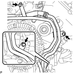
(a) Connect the No. 2 water by-pass pipe with the 3 bolts. Torque: 10 N·m (102 kgf·cm, 7 ft·lbf) |
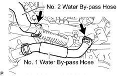
7. CONNECT NO. 2 WATER BY-PASS HOSE
|
(a) Connect the No. 2 water by-pass hose to the water by-pass joint. |
8. CONNECT NO. 1 WATER BY-PASS HOSE
(a) Connect the No. 1 water by-pass hose to the water by-pass joint and water inlet housing.
9. INSTALL NO. 1 ENGINE COVER
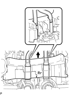
HINT:
- Align the No. 1 engine cover cutouts with the air tube.
- Align the No. 1 engine cover with the air switching valve surface and cylinder head wall.
NOTICE:
Make sure that the No. 1 engine cover is flush with the top surface of the intake port of the cylinder head for bank 1 and bank 2.
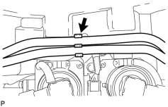
10. CONNECT FUEL TUBE CLAMP
|
(a) Connect the fuel tube clamp to the bracket. |
11. INSTALL NO. 2 ENGINE COVER
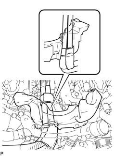
HINT:
- Align the No. 2 engine cover cutout with the air tube.
- Align the No. 2 engine cover with the front water by-pass joint and cylinder head wall.
NOTICE:
Make sure that the No. 2 engine cover is flush with the top surface of the intake port of the cylinder head.
12. INSTALL INTAKE MANIFOLD
(a) Install the intake manifold
 .
.
13. INSTALL EXHAUST MANIFOLD SUB-ASSEMBLY
(a) Install the exhaust manifold
.

|

|