| Last Modified: 11-27-2007 | 1.6 A | |
| Service Category: Vehicle Exterior | Section: Exterior Panels/Trim | |
| Model Year: 2008 | Model: LX570 | Doc ID: RM0000038JZ003X |
| Title: EXTERIOR PANELS / TRIM: FRONT BUMPER: REASSEMBLY (2008 LX570) | ||
REASSEMBLY
HINT:
When installing the front bumper protector, heat the front bumper surface using a heat light.
Standard:
|
Item |
Temperature |
|---|---|
|
Front Bumper |
20 to 30°C (68 to 86°F) |
NOTICE:
Do not heat the front bumper excessively.
1. INSTALL FRONT BUMPER EXTENSION MOUNTING BRACKET
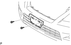
(a) Install the bracket with the 2 screws.
2. INSTALL FRONT BUMPER PROTECTOR
(a) Clean the front bumper surface.
(1) Using a heat light, heat the front bumper surface.
(2) Remove the double-sided tape from the front bumper.
(3) Wipe off any tape adhesive residue with cleaner.
|
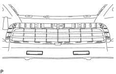
(b) Install a new bumper protector. (1) Remove the peeling paper from the face of 2 new bumper protectors. HINT:
After removing the peeling paper, keep the exposed adhesive free from foreign matter. (2) Install the 2 bumper protectors as shown in the illustration. |
3. INSTALL HEADLIGHT WASHER ACTUATOR SUB-ASSEMBLY LH (w/ Headlight Cleaner System)

4. INSTALL HEADLIGHT WASHER ACTUATOR SUB-ASSEMBLY RH (w/ Headlight Cleaner System)
HINT:
Use the same procedures described for the LH side.
5. INSTALL TYPE 1 HEADLIGHT WASHER NOZZLE SUB-ASSEMBLY LH (w/ Headlight Cleaner System)
6. INSTALL TYPE 1 HEADLIGHT WASHER NOZZLE SUB-ASSEMBLY RH (w/ Headlight Cleaner System)
HINT:
Use the same procedures described for the LH side.
7. INSTALL LOWER RADIATOR GRILLE
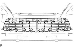
(a) Attach the 16 claws to install the lower radiator grille.
8. INSTALL FRONT BUMPER HOLE COVER LH
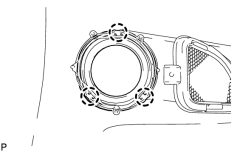
(a) Attach the 3 claws to install the hole cover.
9. INSTALL FRONT BUMPER HOLE COVER RH
HINT:
Use the same procedures described for the LH side.
10. INSTALL FRONT BUMPER GARNISH LH
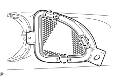
(a) Attach the 3 claws to install the garnish.
11. INSTALL FRONT BUMPER GARNISH RH
HINT:
Use the same procedures described for the LH side.
12. INSTALL FOG LIGHT MOUNTING BRACKET LH
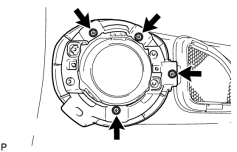
(a) Install the bracket with the 4 screws.
13. INSTALL FOG LIGHT MOUNTING BRACKET RH
HINT:
Use the same procedures described for the LH side.
14. INSTALL FOG LIGHT ASSEMBLY LH
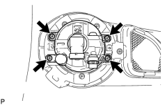
(a) Install the fog light with the 4 screws.
15. INSTALL FOG LIGHT ASSEMBLY RH
HINT:
Use the same procedures described for the LH side.
16. INSTALL NO. 1 ULTRASONIC SENSOR RETAINER (w/ Intuitive Parking Assist System)
17. INSTALL NO. 1 ULTRASONIC SENSOR (w/ Intuitive Parking Assist System)
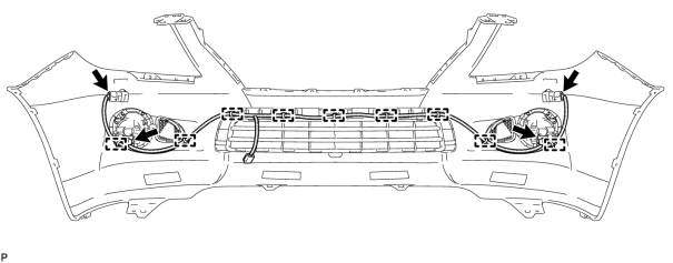
18. INSTALL NO. 4 ENGINE ROOM WIRE
(a) w/o Intuitive Parking Assist System:
Install the No. 4 engine room wire.
(1) Attach the 7 clamps to install the engine room wire.
(2) Connect the 2 connectors.
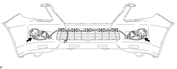
(b) w/ Intuitive Parking Assist System:
Install the No. 4 engine room wire.
(1) Attach the 9 clamps to install the engine room wire.
(2) Connect the 4 connectors.

|

|