| Last Modified: 11-27-2007 | 1.6 A | |
| Service Category: Vehicle Interior | Section: Interior Panels/Trim | |
| Model Year: 2008 | Model: LX570 | Doc ID: RM0000039OQ002X |
| Title: INTERIOR PANELS / TRIM: INSTRUMENT PANEL SAFETY PAD: REMOVAL (2008 LX570) | ||
REMOVAL
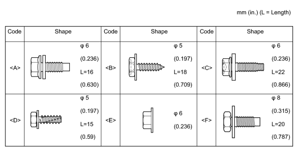
1. TABLE OF BOLT, SCREW AND NUT
HINT:
All bolts, screws and nuts relevant to installing and removing the instrument panel are shown along with their alphabet code in the table below.
2. REMOVE ENGINE ROOM SIDE COVER LH

3. REMOVE ENGINE ROOM SIDE COVER RH
4. REMOVE UPPER RADIATOR SUPPORT SEAL
5. RECOVER REFRIGERANT FROM REFRIGERATION SYSTEM (w/ Cool Box)
6. DISCONNECT CABLE FROM NEGATIVE BATTERY TERMINAL
(a) Disable the Autoaway/Return function by changing the customize parameter
.
NOTICE:
Record the current customize parameter setting (whether the Autoaway/Return function is enabled or disabled) in order to restore the current setting after finishing the operation.
HINT:
Performing the above operation causes the Autoaway/Return function to be disabled when the engine switch is turned off.
(b) Turn the engine switch on (IG). Operate the tilt and telescopic switch to fully extend and lower the steering column.
(c) Turn the engine switch off and disconnect the cable from the negative (-) battery terminal.
CAUTION:
Wait at least 90 seconds after disconnecting the cable from the negative (-) battery terminal to disable the SRS system.
NOTICE:
-
w/ Navigation System:
After the engine switch is turned off, the HDD navigation system requires approximately 6 minutes to record various types of memory and settings. As a result, after turning the engine switch off, wait 6 minutes or more before disconnecting the cable from the negative (-) battery terminal.
-
When disconnecting the cable, some systems need to be initialized after the cable is reconnected
.
7. REMOVE LOWER NO. 3 STEERING WHEEL COVER
8. REMOVE LOWER NO. 2 STEERING WHEEL COVER
9. REMOVE STEERING PAD
10. REMOVE STEERING WHEEL ASSEMBLY
11. REMOVE LOWER STEERING COLUMN COVER
12. REMOVE UPPER STEERING COLUMN COVER
13. REMOVE TILT AND TELESCOPIC SWITCH
14. REMOVE COMBINATION SWITCH ASSEMBLY WITH SPIRAL CABLE SUB-ASSEMBLY
15. REMOVE FRONT SEAT ASSEMBLY LH
(a) Remove the front seat assembly LH
.
16. REMOVE FRONT SEAT ASSEMBLY RH
(a) Remove the front seat assembly RH
.
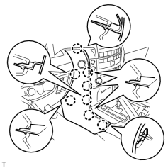
17. REMOVE LOWER INSTRUMENT PANEL PAD SUB-ASSEMBLY LH
|
(a) Detach the 8 claws. |
(b) Disconnect the connector and remove the panel pad.
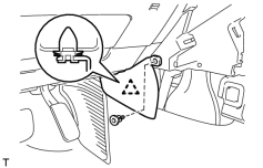
18. REMOVE INNER NO. 1 INSTRUMENT PANEL BRACKET COVER LH
|
(a) Remove the clip. |
(b) Detach the clip and remove the cover.
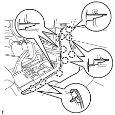
19. REMOVE LOWER INSTRUMENT PANEL PAD SUB-ASSEMBLY RH
|
(a) Detach the 9 claws and remove the panel pad. |
20. REMOVE INNER NO. 1 INSTRUMENT PANEL BRACKET COVER RH
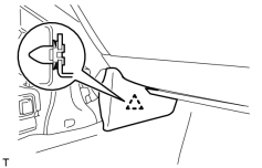
|
(a) Detach the clip and remove the cover. |
21. REMOVE SHIFT LEVER KNOB SUB-ASSEMBLY
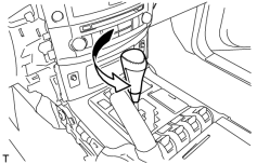
|
(a) Twist the shift lever knob in the direction indicated by the arrow and remove it. |
22. REMOVE LOWER CENTER INSTRUMENT CLUSTER FINISH PANEL SUB-ASSEMBLY
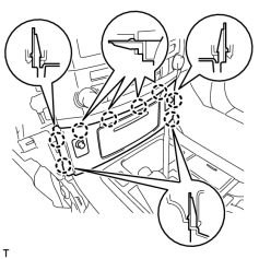
|
(a) Detach the 8 claws. |
(b) Disconnect the connectors and remove the panel.
23. REMOVE PARKING BRAKE HOLE COVER
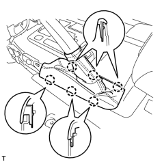
|
(a) Detach the 6 claws and remove the cover. |
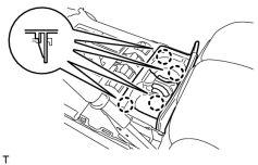
24. REMOVE CONSOLE CUP HOLDER BOX SUB-ASSEMBLY
|
(a) Detach the 4 claws and remove the box. |
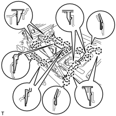
25. REMOVE UPPER CONSOLE PANEL SUB-ASSEMBLY
|
(a) Detach the 13 claws. |
(b) Disconnect the connectors and remove the console panel.
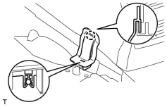
26. REMOVE NO. 1 COOLER COVER (w/ Cool Box)
|
(a) Detach the clamp on the lower part of the cooler cover, and then pull the cooler cover upward to remove it. |
27. REMOVE REAR CONSOLE END PANEL SUB-ASSEMBLY
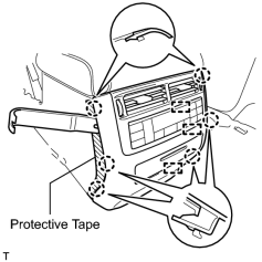
(a) Place protective tape as shown in the illustration.
(b) Using a moulding remover, detach the 6 claws.
(c) Remove the end panel and disconnect the connectors and 3 clamps.
28. REMOVE TELEPHONE ECU ASSEMBLY WITH BRACKET (w/ LEXUS Link System)
29. REMOVE REAR CONSOLE BOX SUB-ASSEMBLY (w/o Cool Box)
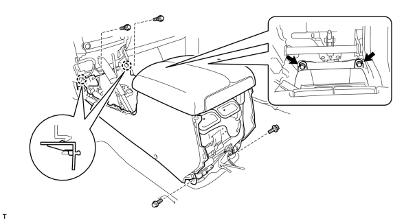
(a) Remove the 4 bolts and 2 screws.
(b) Detach the 2 claws and remove the console box.
30. REMOVE COOLING BOX ASSEMBLY (w/ Cool Box)
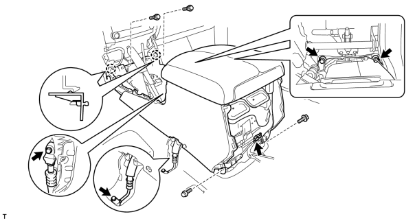
(a) Remove the 4 bolts and 2 screws.
(b) Remove the 2 bolts and disconnect the 2 cooler pipes.
(c) Remove the 2 O-rings from the cooler pipes.
(d) Disconnect the connector.
(e) Detach the 2 claws and remove the cooling box.
31. REMOVE INSTRUMENT SIDE PANEL LH
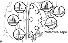
|
(a) Place protective tape as shown in the illustration. |
(b) Using a moulding remover, detach the 6 claws and remove the side panel.
32. REMOVE NO. 1 SWITCH HOLE BASE
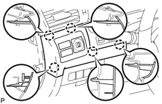
|
(a) Detach the 5 claws. |
(b) Disconnect the connectors and remove the switch hole base.
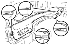
33. REMOVE INSTRUMENT CLUSTER FINISH PANEL SUB-ASSEMBLY
|
(a) Detach the 4 claws. |
(b) Disconnect the connectors and remove the finish panel.
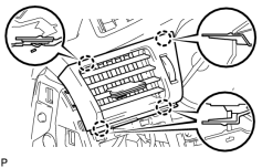
34. REMOVE NO. 1 INSTRUMENT PANEL REGISTER ASSEMBLY
|
(a) Detach the 4 claws and remove the register. |
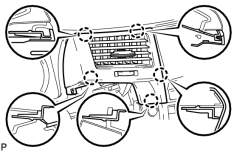
35. REMOVE NO. 3 INSTRUMENT PANEL REGISTER ASSEMBLY
|
(a) Detach the 5 claws and remove the register. |
36. REMOVE COMBINATION METER ASSEMBLY
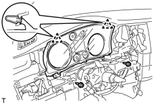
(a) Remove the 2 screws.
(b) Detach the 2 clips.
(c) Disconnect the connector and remove the combination meter.
37. REMOVE FRONT DOOR SCUFF PLATE LH
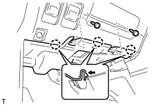
38. REMOVE NO. 1 INSTRUMENT PANEL UNDER COVER SUB-ASSEMBLY
|
(a) Remove the 2 screws. |
(b) Detach the 3 claws.
(c) Remove the under cover and disconnect the connectors.
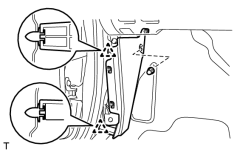
39. REMOVE COWL SIDE TRIM BOARD LH
|
(a) Remove the cap nut. |
(b) Detach the 2 clips and remove the trim board.
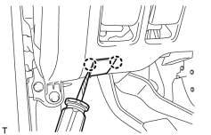
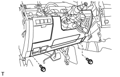
40. REMOVE LOWER NO. 1 INSTRUMENT PANEL FINISH PANEL
|
(a) Using a screwdriver, detach the 2 claws. HINT:
Tape the screwdriver tip before use. |
(b) Open the hole cover.
|
(c) Remove the 2 bolts. |
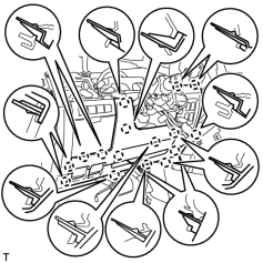
|
(d) Detach the 16 claws. |
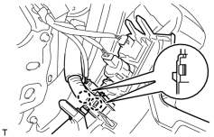
|
(e) Detach the 2 claws and remove the sensor. |
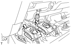
|
(f) Detach the 2 claws and disconnect the 2 control cables. |
(g) Remove the finish panel and then disconnect the connectors.
41. REMOVE INSTRUMENT PANEL BOX ASSEMBLY
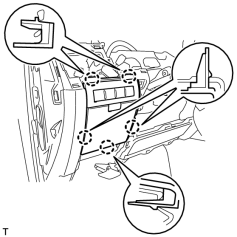
|
(a) Detach the 5 claws. |
(b) Remove the box and then disconnect the connectors.
42. REMOVE DRIVER SIDE KNEE AIRBAG ASSEMBLY
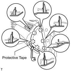
43. REMOVE INSTRUMENT SIDE PANEL RH
|
(a) Place protective tape as shown in the illustration. |
(b) Using a moulding remover, detach the 6 claws and remove the side panel.
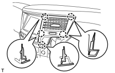
44. REMOVE NO. 4 INSTRUMENT PANEL REGISTER ASSEMBLY
|
(a) Detach the 5 claws and remove the register. |
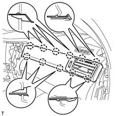
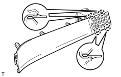
45. REMOVE NO. 3 INSTRUMENT CLUSTER FINISH PANEL GARNISH
|
(a) Detach the 11 claws and remove the register assembly. |
|
(b) Detach the 4 claws and remove the panel garnish. |
46. REMOVE FRONT DOOR SCUFF PLATE RH
47. REMOVE NO. 2 INSTRUMENT PANEL UNDER COVER SUB-ASSEMBLY
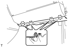
|
(a) Detach the 4 claws. |
(b) Remove the under cover and disconnect the connector.
48. REMOVE COWL SIDE TRIM BOARD RH
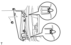
|
(a) Remove the cap nut. |
(b) Detach the 2 clips and remove the trim board.
49. REMOVE FRONT PASSENGER SIDE KNEE AIRBAG ASSEMBLY
50. REMOVE INSTRUMENT PANEL BOX DOOR KNOB
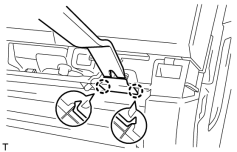
|
(a) Using a moulding remover, detach the 2 claws and remove the knob. |
51. REMOVE LOWER NO. 2 INSTRUMENT PANEL FINISH PANEL
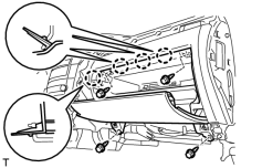
|
(a) Remove the 4 bolts. |
(b) Detach the 4 claws.
(c) Remove the finish panel and then disconnect the connector.
52. REMOVE FRONT ASSIST GRIP SUB-ASSEMBLY
53. REMOVE FRONT PILLAR GARNISH LH
54. REMOVE FRONT PILLAR GARNISH RH
55. REMOVE NO. 1 SPEAKER OPENING COVER ASSEMBLY
56. REMOVE FRONT NO. 4 SPEAKER ASSEMBLY
57. REMOVE NO. 1 INSTRUMENT PANEL SPEAKER PANEL SUB-ASSEMBLY
58. REMOVE FRONT NO. 2 SPEAKER ASSEMBLY (LH Side)
59. REMOVE NO. 2 INSTRUMENT PANEL SPEAKER PANEL SUB-ASSEMBLY
60. REMOVE FRONT NO. 2 SPEAKER ASSEMBLY (RH Side)
61. REMOVE DISPLAY AND NAVIGATION MODULE DISPLAY WITH BRACKET (w/ Navigation System)
62. REMOVE MULTI-DISPLAY ASSEMBLY WITH BRACKET (w/o Navigation System)
63. REMOVE RADIO RECEIVER ASSEMBLY WITH BRACKET
64. REMOVE NO. 1 INSTRUMENT CLUSTER MOULDING
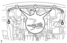
|
(a) Remove the 2 screws. |
(b) Detach the 3 claws and remove the moulding.
65. REMOVE REAR NO. 2 AIR DUCT
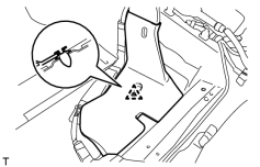
|
(a) Fold back the front floor carpet. |
(b) Detach the clip and remove the air duct.
66. REMOVE REAR NO. 4 AIR DUCT
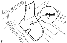
|
(a) Fold back the front floor carpet. |
(b) Detach the clip and remove the air duct.
67. REMOVE INSTRUMENT PANEL SAFETY PAD ASSEMBLY
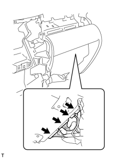
|
(a) w/ Wide View Front and Side Monitor System: Disconnect the connectors. |
(b) Disconnect the connectors and clamps.
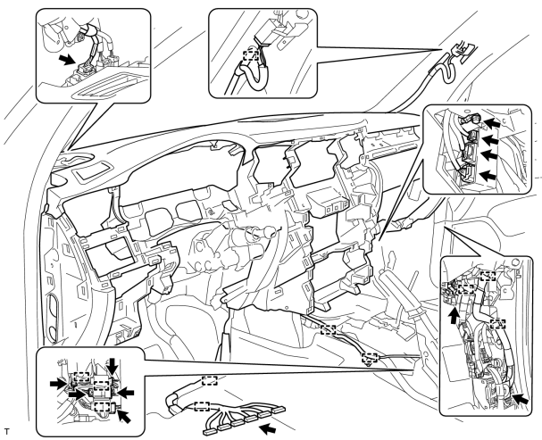
(c) Remove the bolt and disconnect the wire harness.
(d) Remove the 2 passenger airbag bolts.
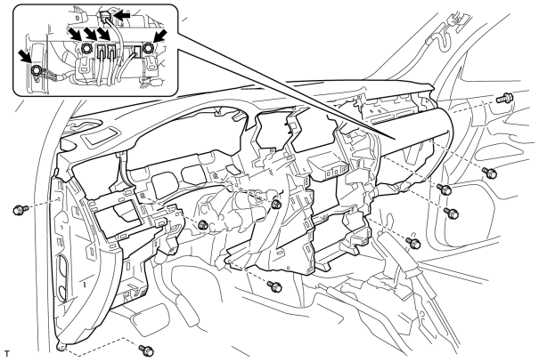
(e) Remove the bolt.
(f) Disconnect the connectors.
(g) Remove the 8 bolts.
(h) Remove the 2 nuts and safety pad.

|

|