| Last Modified: 11-27-2007 | 1.6 A | |
| Service Category: Vehicle Interior | Section: Interior Panels/Trim | |
| Model Year: 2008 | Model: LX570 | Doc ID: RM0000039ON002X |
| Title: INTERIOR PANELS / TRIM: INSTRUMENT PANEL SAFETY PAD: INSTALLATION (2008 LX570) | ||
INSTALLATION
HINT:
A bolt without a torque specification is shown in the standard bolt chart
 .
.
1. INSTALL INSTRUMENT PANEL SAFETY PAD ASSEMBLY
(a) Install the safety pad with the 8 bolts and 2 nuts.
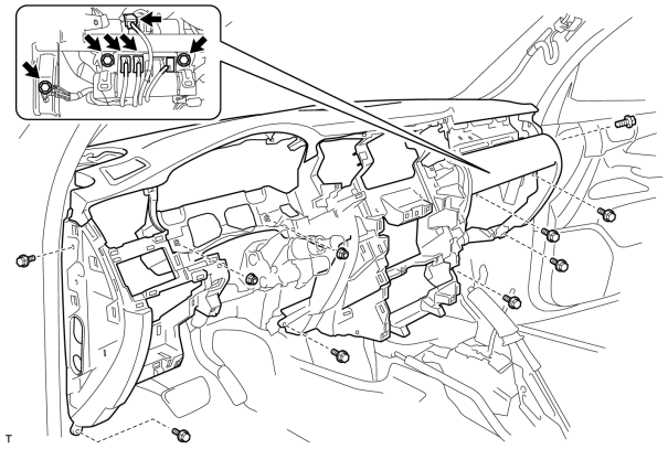
(b) Connect the connectors.
(c) Install the bolt.
(d) Install the 2 passenger airbag bolts.
Torque: 20 N·m (204 kgf·cm, 15 ft·lbf)
(e) Connect the wire harness with the bolt.
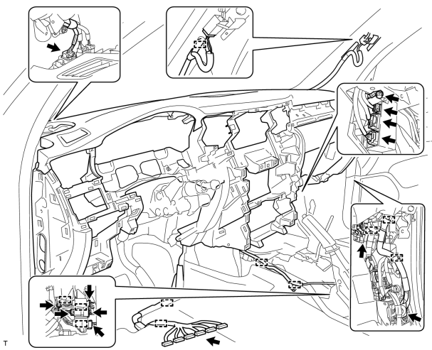
(f) Connect the connectors and clamps.
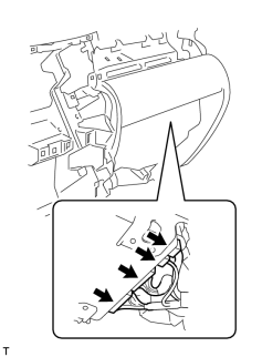
|
(g) w/ Wide View Front and Side Monitor System: Connect the connectors. |
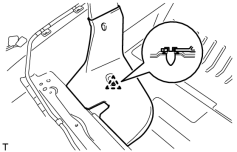
2. INSTALL REAR NO. 4 AIR DUCT
|
(a) Attach the clip to install the air duct. |
3. INSTALL REAR NO. 2 AIR DUCT
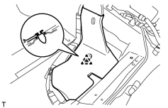
|
(a) Attach the clip to install the air duct. |
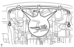
4. INSTALL NO. 1 INSTRUMENT CLUSTER MOULDING
|
(a) Attach the 3 claws to install the moulding. |
(b) Install the 2 screws.
5. INSTALL RADIO RECEIVER ASSEMBLY WITH BRACKET
6. INSTALL MULTI-DISPLAY ASSEMBLY WITH BRACKET (w/o Navigation System)
7. INSTALL DISPLAY AND NAVIGATION MODULE DISPLAY WITH BRACKET (w/ Navigation System)
8. INSTALL FRONT NO. 2 SPEAKER ASSEMBLY (RH Side)
9. INSTALL NO. 2 INSTRUMENT PANEL SPEAKER PANEL SUB-ASSEMBLY
10. INSTALL FRONT NO. 2 SPEAKER ASSEMBLY (LH Side)
11. INSTALL NO. 1 INSTRUMENT PANEL SPEAKER PANEL SUB-ASSEMBLY
12. INSTALL FRONT NO. 4 SPEAKER ASSEMBLY
13. INSTALL NO. 1 SPEAKER OPENING COVER ASSEMBLY
14. INSTALL FRONT PILLAR GARNISH RH
15. INSTALL FRONT PILLAR GARNISH LH
16. INSTALL FRONT ASSIST GRIP SUB-ASSEMBLY
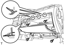
17. INSTALL LOWER NO. 2 INSTRUMENT PANEL FINISH PANEL
|
(a) Connect the connector. |
(b) Attach the 4 claws to install the finish panel.
(c) Install the 4 bolts.
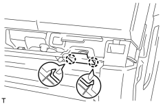
18. INSTALL INSTRUMENT PANEL BOX DOOR KNOB
|
(a) Attach the 2 claws to install the knob. |
19. INSTALL FRONT PASSENGER SIDE KNEE AIRBAG ASSEMBLY
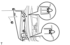
20. INSTALL COWL SIDE TRIM BOARD RH
|
(a) Attach the 2 clips to install the trim board. |
(b) Install the cap nut.
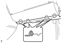
21. INSTALL NO. 2 INSTRUMENT PANEL UNDER COVER SUB-ASSEMBLY
|
(a) Connect the connector. |
(b) Attach the 4 claws to install the under cover.
22. INSTALL FRONT DOOR SCUFF PLATE RH
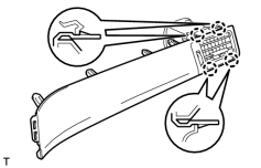
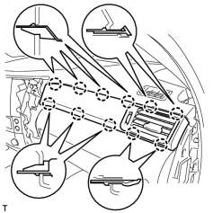
23. INSTALL NO. 3 INSTRUMENT CLUSTER FINISH PANEL GARNISH
|
(a) Attach the 4 claws and install the panel garnish. |
|
(b) Attach the 11 claws to install the register assembly. |
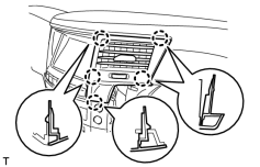
24. INSTALL NO. 4 INSTRUMENT PANEL REGISTER ASSEMBLY
|
(a) Attach the 5 claws to install the register. |
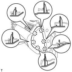
25. INSTALL INSTRUMENT SIDE PANEL RH
|
(a) Attach the 6 claws to install the side panel. |
26. INSTALL DRIVER SIDE KNEE AIRBAG ASSEMBLY
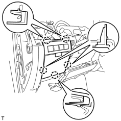
27. INSTALL INSTRUMENT PANEL BOX ASSEMBLY
|
(a) Connect the connectors. |
(b) Attach the 5 claws to install the box.
28. INSTALL LOWER NO. 1 INSTRUMENT PANEL FINISH PANEL
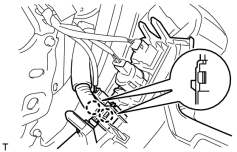
(a) Connect the connectors.
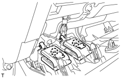
(b) Attach the 2 claws to install the sensor.
|
(c) Attach the 2 claws to connect the 2 control cables. |
|
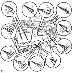
(d) Attach the 16 claws to install the finish panel. |
|
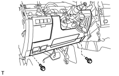
(e) Install the 2 bolts. |
|
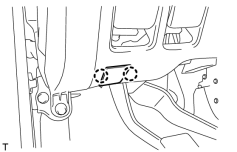
(f) Attach the 2 claws to close the hole cover. |
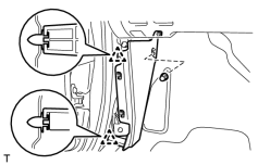
29. INSTALL COWL SIDE TRIM BOARD LH
|
(a) Attach the 2 clips to install the trim board. |
(b) Install the cap nut.
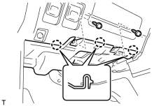
30. INSTALL NO. 1 INSTRUMENT PANEL UNDER COVER SUB-ASSEMBLY
|
(a) Connect the connectors. |
(b) Attach the 3 claws to install the under cover.
(c) Install the 2 screws.
31. INSTALL FRONT DOOR SCUFF PLATE LH
32. INSTALL COMBINATION METER ASSEMBLY
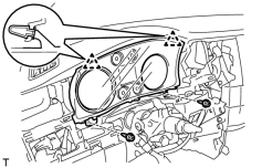
(a) Connect the connector.
(b) Attach the 2 clips to install the combination meter.
(c) Install the 2 screws.
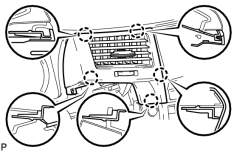
33. INSTALL NO. 3 INSTRUMENT PANEL REGISTER ASSEMBLY
|
(a) Attach the 5 claws to install the register. |
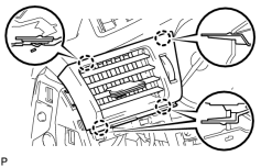
34. INSTALL NO. 1 INSTRUMENT PANEL REGISTER ASSEMBLY
|
(a) Attach the 4 claws to install the register. |
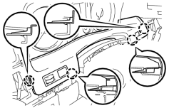
35. INSTALL INSTRUMENT CLUSTER FINISH PANEL SUB-ASSEMBLY
|
(a) Connect the connectors. |
(b) Attach the 4 claws to install the finish panel.
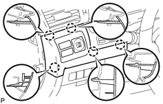
36. INSTALL NO. 1 SWITCH HOLE BASE
|
(a) Connect the connectors. |
(b) Attach the 5 claws to install the switch hole base.
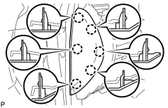
37. INSTALL INSTRUMENT SIDE PANEL LH
|
(a) Attach the 6 claws to install the side panel. |
38. INSTALL COOLING BOX ASSEMBLY (w/ Cool Box)
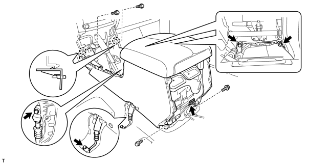
(a) Attach the 2 claws.
(b) Connect the connector.
(c) Sufficiently apply compressor oil to 2 new O-rings.
Compressor oil:
ND-OIL 8 or equivalent
(d) Install the 2 O-rings to the 2 cooler pipes.
(e) Connect the 2 cooler pipes with the 2 bolts.
Torque: 9.8 N·m (100 kgf·cm, 87 in·lbf)
(f) Install the cooling box with the 4 bolts and 2 screws.
39. INSTALL REAR CONSOLE BOX SUB-ASSEMBLY (w/o Cool Box)
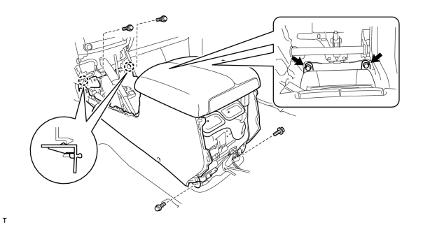
(a) Attach the 2 claws.
(b) Install the console box with the 4 bolts and 2 screws.
40. INSTALL TELEPHONE ECU ASSEMBLY WITH BRACKET (w/ LEXUS Link System)
41. INSTALL REAR CONSOLE END PANEL SUB-ASSEMBLY
|
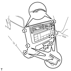
(a) Connect the connectors and 3 clamps. |
(b) Attach the 6 claws to install the end panel.
42. INSTALL NO. 1 COOLER COVER (w/ Cool Box)
|
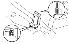
(a) Attach the claw on the upper part of the cooler cover, and then attach the clamp on the lower part of the cooler cover to install it. |
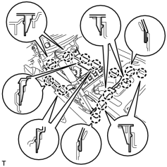
43. INSTALL UPPER CONSOLE PANEL SUB-ASSEMBLY
|
(a) Connect the connectors. |
(b) Attach the 13 claws to install the console panel.
44. INSTALL CONSOLE CUP HOLDER BOX SUB-ASSEMBLY
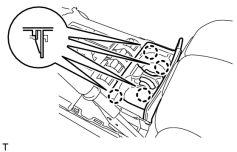
|
(a) Attach the 4 claws to install the box. |
45. INSTALL PARKING BRAKE HOLE COVER
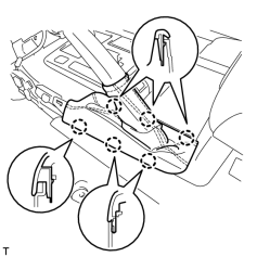
|
(a) Attach the 6 claws to install the cover. |
46. INSTALL LOWER CENTER INSTRUMENT CLUSTER FINISH PANEL SUB-ASSEMBLY
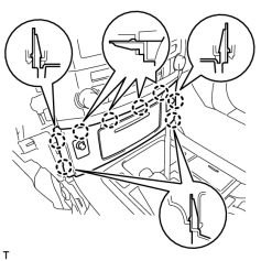
|
(a) Connect the connectors. |
(b) Attach the 8 claws to install the panel.
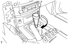
47. INSTALL SHIFT LEVER KNOB SUB-ASSEMBLY
|
(a) Install the shift lever knob and twist it in the direction indicated by the arrow. |
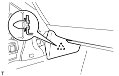
48. INSTALL INNER NO. 1 INSTRUMENT PANEL BRACKET COVER RH
|
(a) Attach the clip to install the cover. |
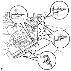
49. INSTALL LOWER INSTRUMENT PANEL PAD SUB-ASSEMBLY RH
|
(a) Attach the 9 claws to install the panel pad. |
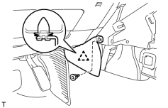
50. INSTALL INNER NO. 1 INSTRUMENT PANEL BRACKET COVER LH
|
(a) Attach the clip to install the cover. |
(b) Install the clip.
51. INSTALL LOWER INSTRUMENT PANEL PAD SUB-ASSEMBLY LH
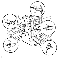
|
(a) Connect the connector. |
(b) Attach the 8 claws to install the panel pad.
52. INSTALL FRONT SEAT ASSEMBLY RH
(a) Install the front seat assembly RH
.
53. INSTALL FRONT SEAT ASSEMBLY LH
(a) Install the front seat assembly LH
.
54. INSTALL COMBINATION SWITCH ASSEMBLY WITH SPIRAL CABLE SUB-ASSEMBLY
55. INSTALL TILT AND TELESCOPIC SWITCH
56. INSTALL UPPER STEERING COLUMN COVER
57. INSTALL LOWER STEERING COLUMN COVER
58. INSTALL STEERING WHEEL ASSEMBLY
59. INSTALL STEERING PAD
60. INSTALL LOWER NO. 2 STEERING WHEEL COVER
61. INSTALL LOWER NO. 3 STEERING WHEEL COVER
62. CONNECT CABLE TO NEGATIVE BATTERY TERMINAL
NOTICE:
-
Reset the Autoaway/Return function setting to the previous condition by changing the customize parameter
.
-
When disconnecting the cable, some systems need to be initialized after the cable is reconnected
.
63. CHARGE REFRIGERANT (w/ Cool Box)
64. WARM UP ENGINE (w/ Cool Box)
65. CHECK FOR REFRIGERANT GAS LEAK
66. INSTALL UPPER RADIATOR SUPPORT SEAL
67. INSTALL ENGINE ROOM SIDE COVER RH
68. INSTALL ENGINE ROOM SIDE COVER LH
69. CHECK SRS WARNING LIGHT
(a) Check the SRS warning light
.

|

|