| Last Modified: 11-27-2007 | 1.6 A | |
| Service Category: Steering | Section: Steering Column | |
| Model Year: 2008 | Model: LX570 | Doc ID: RM0000039SG004X |
| Title: VARIABLE GEAR RATIO STEERING: STEERING ACTUATOR: INSTALLATION (2008 LX570) | ||
INSTALLATION
1. HANDLING PRECAUTIONS FOR STEERING ACTUATOR ASSEMBLY
NOTICE:
- Be careful that the No. 2 seal lip or boot does not turn outward while carrying or installing the steering actuator assembly. If installing a new steering actuator assembly, make sure that the spiral center lock pin is securely inserted.
-
Do not use the steering actuator assembly if it has been dropped.
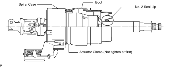
2. INSTALL STEERING ACTUATOR ASSEMBLY
(a) Make sure that the power steering link assembly is centered.
|
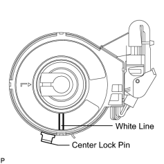
(b) Install the steering actuator assembly. (1) If installing a new steering actuator assembly: Install the steering actuator assembly with the white line on the upper surface of the spiral case facing down. NOTICE:
Do not pull out the center lock pin. (2) If reinstalling the removed steering actuator assembly:
|
|
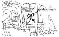
(c) Align the matchmarks on the No. 2 steering intermediate shaft and steering actuator. HINT:
Install the steering actuator from the inside of the vehicle. NOTICE:
|
(d) Install the bolt.
Torque: 35 N·m (360 kgf·cm, 26 ft·lbf)
|
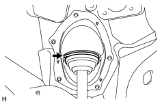
(e) Using needle nose pliers, lock the clamp to the steering column hole cover to install it. NOTICE:
Be careful when performing the operation as the clamp may not lock if the claws of the clamp are deformed. |
|
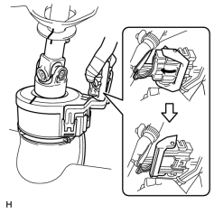
(f) Move the lock in the direction of the arrow and connect the steering actuator connector. HINT:
When a new actuator is installed, remove the center lock pin. |
(g) Connect the connector.
3. INSTALL STEERING COLUMN ASSEMBLY
(a) Install the steering column
 .
.
4. PERFORM VARIABLE GEAR RATIO STEERING SYSTEM CALIBRATION
(a) Perform variable gear ratio steering system calibration
.

|

|