| Last Modified: 11-27-2007 | 1.6 A | |
| Service Category: Steering | Section: Steering Column | |
| Model Year: 2008 | Model: LX570 | Doc ID: RM0000039SG005X |
| Title: STEERING COLUMN: STEERING COLUMN ASSEMBLY: INSTALLATION (2008 LX570) | ||
INSTALLATION
1. CONNECT NO. 2 STEERING INTERMEDIATE SHAFT
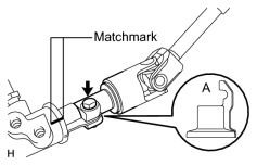
(a) Align the part of the dust cover labeled A with the No. 2 steering intermediate shaft, and install the No. 2 steering intermediate shaft assembly to the steering link assembly.
(b) Install the bolt.
Torque: 35 N·m (360 kgf·cm, 26 ft·lbf)
NOTICE:
Be careful not to damage the dust cover.
2. INSTALL STEERING COLUMN HOLE COVER SUB-ASSEMBLY
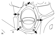
(a) Install the steering column hole cover with the 4 bolts and nut.
Torque: 5.0 N·m (51 kgf·cm, 44 in·lbf)
HINT:
Install the steering intermediate shaft assembly from the inside of the vehicle.
(b) Install the clamp to the steering column hole cover.
3. CONNECT STEERING ACTUATOR ASSEMBLY

4. INSTALL STEERING COLUMN ASSEMBLY
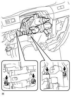
(a) Install the and steering column with the 4 nuts.
Torque: 26 N·m (265 kgf·cm, 19 ft·lbf)
5. INSTALL NO. 3 AIR DUCT SUB-ASSEMBLY
6. CONNECT WIRE HARNESS PROTECTOR AND WIRE HARNESS
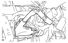
(a) Attach the 3 claws to connect the wiring harness protector and wire harness.
7. INSTALL DRIVER SIDE KNEE AIRBAG ASSEMBLY
8. INSTALL INSTRUMENT PANEL BOX ASSEMBLY
9. INSTALL LOWER NO. 1 INSTRUMENT PANEL FINISH PANEL
10. INSTALL COWL SIDE TRIM BOARD LH
11. INSTALL NO. 1 INSTRUMENT PANEL UNDER COVER SUB-ASSEMBLY
12. INSTALL FRONT DOOR SCUFF PLATE LH
13. INSTALL NO. 3 INSTRUMENT PANEL REGISTER ASSEMBLY
14. INSTALL NO. 1 INSTRUMENT PANEL REGISTER ASSEMBLY
15. INSTALL INSTRUMENT CLUSTER FINISH PANEL SUB-ASSEMBLY
16. INSTALL NO. 1 SWITCH HOLE BASE
17. INSTALL INSTRUMENT SIDE PANEL LH
18. INSTALL INNER NO. 1 INSTRUMENT PANEL BRACKET COVER LH
19. INSTALL LOWER INSTRUMENT PANEL PAD SUB-ASSEMBLY LH
20. INSTALL COMBINATION SWITCH ASSEMBLY WITH SPIRAL CABLE SUB-ASSEMBLY
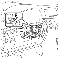
(a) Using pliers, grip the claws of the clamp and install the turn signal switch assembly with spiral cable sub-assembly to the steering column assembly with the clamp.
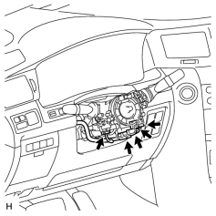
|
(b) Connect the 5 connectors to the turn signal switch with spiral cable. |
21. INSTALL TILT AND TELESCOPIC MANUAL SWITCH
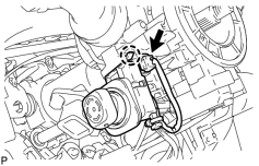
(a) Attach the claw to install the switch.
(b) Connect the switch connector.
22. INSTALL UPPER STEERING COLUMN COVER
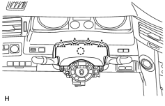
(a) Attach the claw to install the upper steering column cover.
(b) Attach the 4 clips to install the upper steering column cover onto the instrument cluster finish panel.
23. INSTALL LOWER STEERING COLUMN COVER
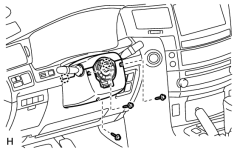
(a) Attach the 2 claws to install the lower steering column cover.
NOTICE:
Do not damage the tilt and telescopic switch.
(b) Install the 3 screws.
Torque: 1.5 N·m (15 kgf·cm, 13 in·lbf)
24. INSTALL STEERING WHEEL ASSEMBLY
25. INSTALL STEERING PAD
26. INSTALL LOWER NO. 2 STEERING WHEEL COVER
27. INSTALL LOWER NO. 3 STEERING WHEEL COVER
28. CHECK FRONT WHEELS FACING STRAIGHT AHEAD
29. INSTALL FRONT WHEELS
30. CONNECT CABLE TO NEGATIVE BATTERY TERMINAL
NOTICE:
Reset the Autoaway/Return function setting to the previous condition by changing the customize parameter
.
31. INSPECT SRS WARNING LIGHT
(a) Inspect the SRS warning light
.
32. PERFORM VARIABLE GEAR RATIO STEERING SYSTEM CALIBRATION
(a) Perform variable gear ratio steering system calibration
.

|

|