| Last Modified: 11-27-2007 | 1.6 A | |
| Service Category: Suspension | Section: Front Suspension | |
| Model Year: 2008 | Model: LX570 | Doc ID: RM000003DGC001X |
| Title: FRONT SUSPENSION: FRONT STABILIZER BAR: INSTALLATION (2008 LX570) | ||
INSTALLATION
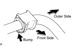
1. INSTALL FRONT NO. 1 STABILIZER BAR BUSH
|
(a) Install the 2 bushes to the outer side of the bush stoppers on the front stabilizer bar as shown in the illustration. NOTICE:
Be sure to install the front No. 1 stabilizer bar bushes so that the cut and bump of each bush faces the under of the vehicle. |
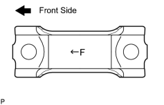
2. INSTALL FRONT STABILIZER BAR
|
(a) Set the stabilizer bracket so that the arrow mark is facing the front side of the vehicle. |
|
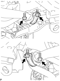
(b) Temporarily install the 2 stabilizer brackets and front stabilizer bar with the 4 bolts. |
3. TEMPORARILY INSTALL FRONT STABILIZER LINK ASSEMBLY LH
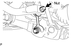
(a) Temporarily install the stabilizer link with the nut and bolt.
|
(b) Tighten the nut. Torque: 128 N·m (1305 kgf·cm, 94 ft·lbf) |
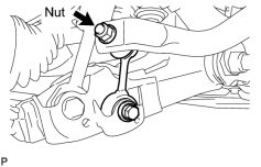
4. TEMPORARILY INSTALL FRONT STABILIZER LINK ASSEMBLY RH
|
(a) Temporarily install the stabilizer link with the nut and bolt. |
(b) Tighten the nut.
Torque: 128 N·m (1305 kgf·cm, 94 ft·lbf)
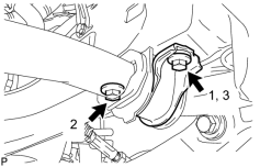
5. TIGHTEN FRONT NO. 1 STABILIZER BRACKET LH
|
(a) Tighten the 2 bolts. Torque: 87 N·m (887 kgf·cm, 64 ft·lbf) HINT:
Tighten the bolts in 3 steps, in the order shown in the illustration. |
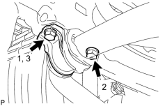
6. TIGHTEN FRONT NO. 1 STABILIZER BRACKET RH
|
(a) Tighten the 2 bolts. Torque: 87 N·m (887 kgf·cm, 64 ft·lbf) HINT:
Tighten the bolts in 3 steps, in the order shown in the illustration. |
7. INSTALL NO. 1 ENGINE UNDER COVER SUB-ASSEMBLY

8. INSTALL FRONT FENDER SPLASH SHIELD SUB-ASSEMBLY LH
9. INSTALL FRONT FENDER SPLASH SHIELD SUB-ASSEMBLY RH
10. STABILIZE SUSPENSION
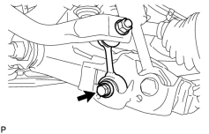
11. TIGHTEN FRONT STABILIZER LINK ASSEMBLY LH
|
(a) Tighten the bolt. Torque: 135 N·m (1376 kgf·cm, 100 ft·lbf) NOTICE:
Perform this procedure with all 4 wheels on the ground. |
12. TIGHTEN FRONT STABILIZER LINK ASSEMBLY RH
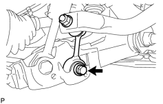
|
(a) Tighten the bolt. Torque: 135 N·m (1376 kgf·cm, 100 ft·lbf) NOTICE:
Perform this procedure with all 4 wheels on the ground. |

|

|