P0115 Step 1
Diagnostic trouble codes
DESCRIPTION
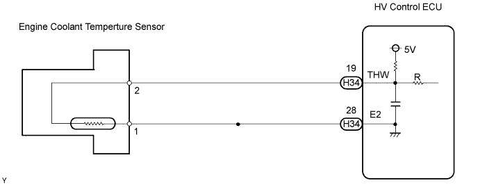
A thermistor is built into the Engine Coolant Temperature (ECT) sensor, of which the resistance value varies according to the ECT.The structure of the sensor and its connection to the ECM (Included in HV Control ECU) are the same as those of the Intake Air Temperature (IAT) sensor.
- HINT:
- When any of DTCs P0115, P0117 and P0118 are set, the ECM enters fail-safe mode. During fail-safe mode, the ECT is estimated to be 80°C (176°F) by the ECM. Fail-safe mode continues until a pass condition is detected.
| DTC No. |
Proceed to |
DTC Detection Condition |
Trouble Area |
| P0115 |
Step 1 |
Open or short in Engine Coolant Temperature (ECT) sensor circuit for 0.5 seconds (1 trip detection logic) |
|
| P0117 |
Step 4 |
Short in Engine Coolant Temperature (ECT) sensor circuit for 0.5 seconds (1 trip detection logic) |
|
| P0118 |
Step 2 |
Open in Engine Coolant Temperature (ECT) sensor circuit for 0.5 seconds (1 trip detection logic) |
|
- HINT:
- When any of these DTCs are set, check the ECT by entering the following menus on the intelligent tester: Powertrain / Engine / Data List / Coolant Temp.
Temperature Displayed
Malfunction
-40°C (-40°F)
Open circuit
140°C (284°F) or higher
Short circuit
WIRING DIAGRAM

INSPECTION PROCEDURE
- HINT:
- If other DTCs relating to different systems that have terminal E2 as the ground terminal are output simultaneously, terminal E2 may have an open circuit.
- Read freeze frame data using the intelligent tester. The ECM records vehicle and driving condition information as freeze frame data the moment a DTC is stored. When troubleshooting, freeze frame data can help determine if the vehicle was moving or stationary, if the engine was warmed up or not, if the air-fuel ratio was lean or rich, and other data, from the time the malfunction occurred.
- If other DTCs relating to different systems that have terminal E2 as the ground terminal are output simultaneously, terminal E2 may have an open circuit.
| 1. READ VALUE USING INTELLIGENT TESTER (ENGINE COOLANT TEMPERATURE) |

Connect the intelligent tester to the DLC3.
Turn the ignition switch ON.
Turn the tester ON.
Enter the following menus: Powertrain / Engine / Data List / Coolant Temp.
Read the value displayed on the tester.
- Standard:
- Between 80°C and 97°C (176°F and 207°F) with warm engine.
- Result:
Temperature Displayed
Proceed to
-40°C (-40°F)
A
140°C (284°F) or higher
B
Between 80°C and 97°C (176°F and 207°F)
C
- HINT:
- If there is an open circuit, the intelligent tester indicates -40°C (-40°F).
- If there is a short circuit, the intelligent tester indicates 140°C (284°F) or higher.
- If there is an open circuit, the intelligent tester indicates -40°C (-40°F).
|
|
||||
|
|
||||


| A | |
 |
| 2. READ VALUE USING INTELLIGENT TESTER (CHECK FOR OPEN IN WIRE HARNESS) |
Remove the w/ converter inverter assembly (Click here).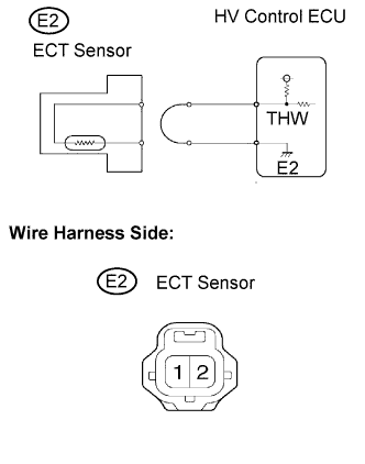
Disconnect the E2 Engine Coolant Temperature (ECT) sensor connector.
Connect terminals 1 and 2 of the ECT sensor connector on the wire harness side.
Connect the intelligent tester to the DLC3.
Turn the ignition switch ON.
Turn the tester ON.
Enter the following menus: Powertrain / Engine / Data List / Coolant Temp.
Read the value displayed on the tester.
- Standard:
- 140°C (284°F) or higher.
Reconnect the ECT sensor connector.
Reinstall the w/ converter inverter assembly (Click here).
Clear the DTC of the HV control system (Click here).
|
|
||||
| NG | |
|
| 3. READ VALUE USING INTELLIGENT TESTER (CHECK FOR OPEN IN ECM (INCLUDED IN HV CONTROL ECU)) |
Remove the w/ converter inverter assembly (Click here).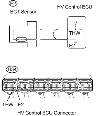
Disconnect the E2 ECT sensor connector.
Connect terminals THW and E2 of the H34 HV Control ECU connector.
- HINT:
- Before checking, do visual and contact pressure checks on the HV Control ECU connector.
Connect the intelligent tester to the DLC3.
Turn the ignition switch ON.
Turn the tester ON.
Enter the following menus: Powertrain / Engine / Data List / Coolant Temp.
Read the value displayed on the tester.
- Standard:
- 140°C (284°F) or higher.
Reconnect the ECT sensor connector.
Reinstall the w/ converter inverter assembly (Click here).
Clear the DTC of the HV control system (Click here).
|
|
||||
| NG | ||
 |
||
| ||
| 4. READ VALUE USING INTELLIGENT TESTER (CHECK FOR SHORT IN WIRE HARNESS) |
Remove the w/ converter inverter assembly (Click here).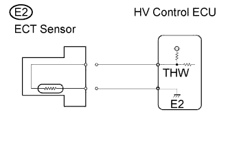
Disconnect the E2 ECT sensor connector.
Connect the intelligent tester to the DLC3.
Turn the ignition switch ON.
Turn the tester ON.
Enter the following menus: Powertrain / Engine / Data List / Coolant Temp.
Read the value displayed on the tester.
- Standard:
- -40°C (-40°F)
Reconnect the ECT sensor connector.
Reinstall the w/ converter inverter assembly (Click here).
Clear the DTC of the HV control system (Click here).
|
|
||||
| NG | |
|
| 5. READ VALUE USING INTELLIGENT TESTER (CHECK FOR SHORT IN ECM (INCLUDED IN HV CONTROL ECU) ) |
Remove the w/ converter inverter assembly (Click here).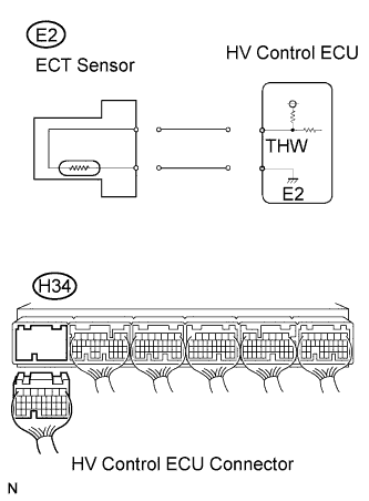
Disconnect the H34 HV Control ECU connectors.
Connect the intelligent tester to the DLC3.
Turn the ignition switch ON.
Turn the tester ON.
Enter the following menus: Powertrain / Engine / Data List / Coolant Temp.
Read the value displayed on the tester.
- Standard:
- -40°C (-40°F)
Reconnect the HV Control ECU connector.
Reinstall the w/ converter inverter assembly (Click here).
Clear the DTC of the HV control system (Click here).
|
|
||||
| NG | ||
|
||
| ||