Headlight Cleaner Switch Circuit
Circuit diagnosis
DESCRIPTION
This circuit sends the signal for the headlight cleaner control relay to operate the headlight cleaner motor and pump assembly. The signal is send when the headlight cleaner switch or the front washer switch is turned ON.The headlight cleaner does not work while the multiplex network body computer sends the signal that the daytime running light system is in operation.
WIRING DIAGRAM
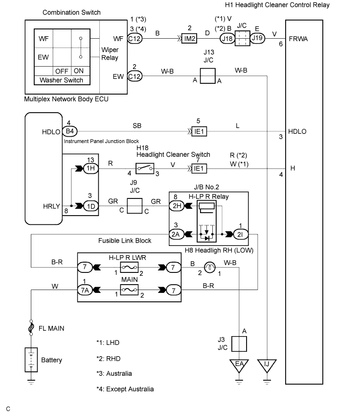

INSPECTION PROCEDURE
| 1. INSPECT HEADLIGHT CLEANER CONTROL RELAY |

Disconnect the connector from the headlight cleaner control relay.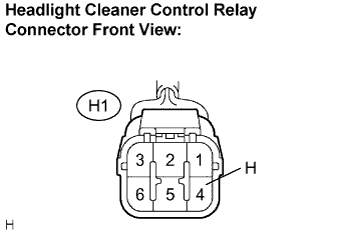
Measure the voltage according to the value(s) in the table below.
- Standard voltage:
Tester Connection
Condition
Specified Condition
H - Body ground
light control switch HEAD, headlight cleaner switch OFF → ON
Below 1 V → 10 to 14 V
|
|
||||

| OK | |
 |
| 2. INSPECT HEADLIGHT CLEANER CONTROL RELAY |
Measure the voltage according to the value(s) in the table below.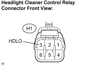
- Standard voltage:
Tester Connection
Condition
Specified Condition
HDLO - Body ground
Engine idling, parking brake released, Light control switch OFF and shift in any position other than P position.
10 to 14 V
|
|
||||
| OK | |
|
| 3. INSPECT HEADLIGHT CLEANER CONTROL RELAY |
Measure the resistance according to the value(s) in the table below.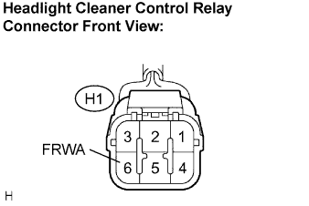
- Standard resistance :
Tester Connection
Condition
Specified Condition
FRWA - Body ground
Front washer switch OFF → ON
10 kΩ or higher → Below 1 Ω
|
|
||||
| OK | ||
 |
||
| ||
| 4. INSPECT HEADLIGHT CLEANER SWITCH ASSEMBLY |
Disconnect the connector from the headlight cleaner switch.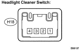
Measure the resistance according to the value(s) in the table below.
- Standard resistance:
Tester Connection
Condition
Specified Condition
4 - 3
Headlight cleaner switch not pushed → pushed
10 kΩ or higher → Below 1 Ω
|
|
||||

| OK | |
|
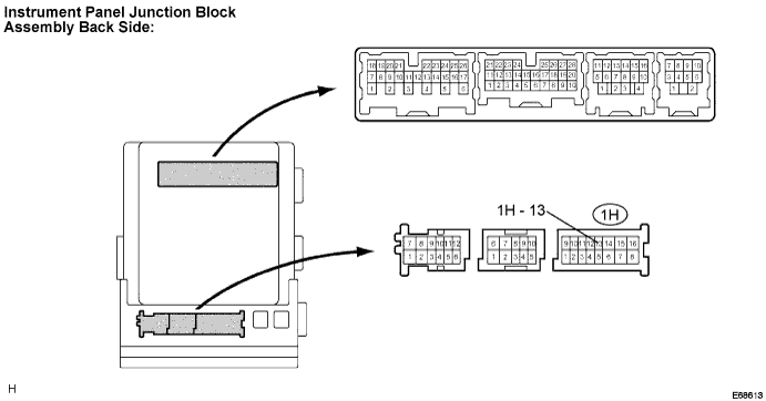
| 5. CHECK HARNESS AND CONNECTOR (HEADLIGHT CLEANER CONTROL RELAY - INSTRUMENT PANEL J/B)) |
Disconnect the connector from the headlight cleaner control relay and instrument panel J/B.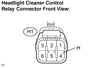
Measure the resistance according to the value(s) in the table below.
- Standard resistance:
Tester Connection
Condition
Specified Condition
H - 1H-13
Headlight cleaner switch not pushed → pushed
10 kΩ or higher → Below 1 Ω
H - Body ground
Always
10 kΩ or higher
|
|
||||
| OK | ||
|
||
| ||
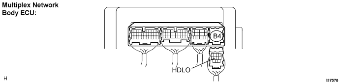
| 6. CHECK HARNESS AND CONNECTOR (HEADLIGHT CLEANER CONTROL RELAY - BODY ECU) |
Disconnect the connector from the headlight cleaner and multiplex network body ECU.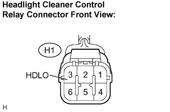
Measure the resistance according to the value(s) in the table below.
- Standard resistance:
Tester Connection
Condition
Specified Condition
HDLO - HDLO
Always
Below 1 Ω
HDLO - Body ground
Always
10 kΩ or higher
|
|
||||
| OK | ||
|
||
| ||
| 7. INSPECT WINDSHIELD WIPER SWITCH ASSEMBLY |
Inspect the windshield wiper switch assembly (Click here).
|
|
||||
| OK | ||
|
||
| ||