Rain Sensor Circuit
Circuit diagnosis
DESCRIPTION
This circuit provides power to operate the rain sensor.The auto wiper system operates when the wiper switch is in the AUTO position.
The rain sensor is connected to each ECU through the multiplex communication line.
When the rain sensor detects raindrops in the detection area of the windshield glass, the sensor sends a wiper control signal according to the amount of raindrops to the windshield wiper relay assembly.
When the rain sensor malfunctions, DTC of multiplex communication systems can be seen at the same time.
WIRING DIAGRAM
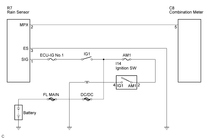

INSPECTION PROCEDURE
| 1. INSPECT FUSE |

Inspect the AM1, ECU-IG No.1 and INP-J/B fuses.
Measure the resistance between each terminals.
- Standard resistance:
- Below 1Ω
|
|
||||

| OK | |
 |
| 2. CHECK HARNESS AND CONNECTOR (RAIN SENSOR - BODY GROUND) |
Disconnect the connector from the rain sensor.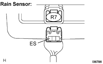
Measure the resistance according to the value(s) in the table below.
- Standard resistance:
Tester Connection
Condition
Specified Condition
ES - Body ground
Always
Below 1 Ω
|
|
||||
| OK | |
|
| 3. INSPECT RAIN SENSOR (RAIN SENSOR - OVERHEAD JUNCTION BLOCK) |
Disconnect the connector from the rain sensor.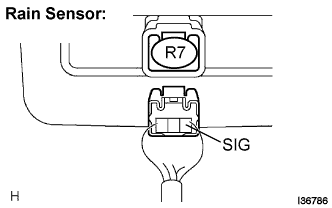
Measure the voltage according to the value(s) in the table below.
- Standard voltage:
Tester Connection
Condition
Specified Condition
SIG - Body ground
Ignition switch
OFF → ON
Below 1 V → 10 to 14 V
|
|
||||
| OK | ||
 |
||
| ||