Wiper and Washer Switch Circuit
Circuit diagnosis
DESCRIPTION
This circuit detects the state of the wiper and washer switch and sends it to the windshield wiper relay assembly.WIRING DIAGRAM
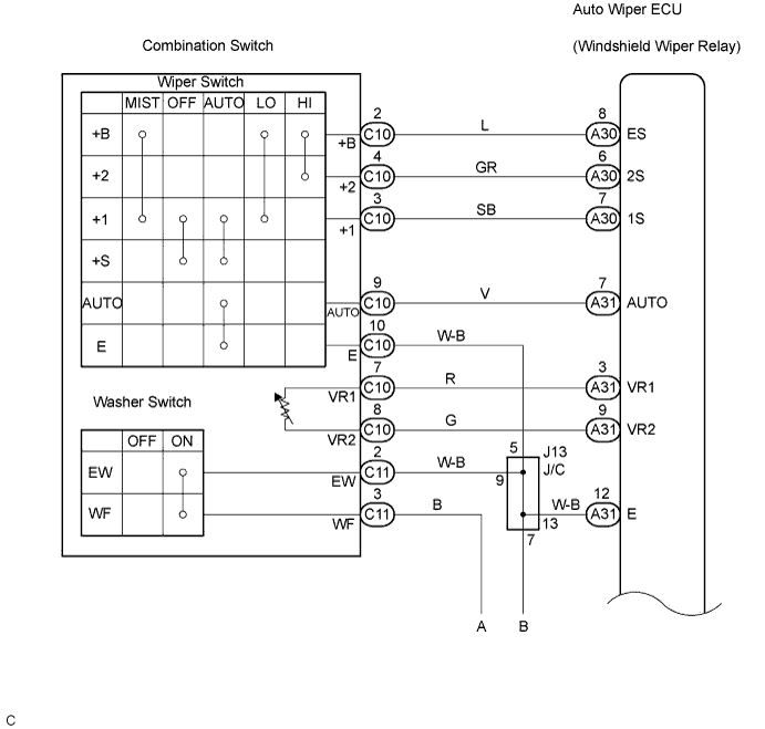

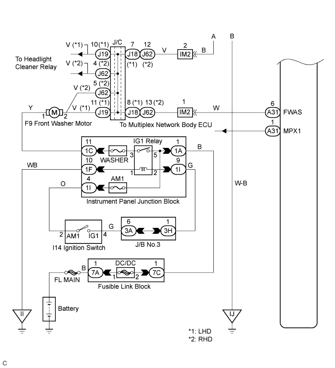
INSPECTION PROCEDURE
- HINT:
- Start the inspection from step 1 when using the intelligent tester, and start from step 2 when not using the intelligent tester.
| 1. READ VALUE OF INTELLIGENT TESTER |

Connect the intelligent tester to the DLC3.
Turn the ignition switch to the ON position and turn the tester main switch on.
Select the items below in the DATA LIST, and read the displays on the intelligent tester.
Wiper: Item
Measurement Item/ Display (Range)
Normal Condition
Diagnostic Note
WIPER LO SW
Wiper LO switch input/ON or OFF
ON: Front wiper switch is in LO position
OFF: Front wiper switch is in any position other than LO
-
WIPER HI SW
Wiper HI switch input/ ON or OFF
ON: Front wiper switch in HI position
OFF: Front wiper switch is in any position other than HI
-
WIPER AUTO SW
Wiper AUTO switch input/ ON or OFF
ON: Front wiper switch is in AUTO position
OFF: Front switch is in any position other than AUTO
-
|
|
||||

| OK | ||
 |
||
| ||
| 2. INSPECT WINDSHIELD WIPER SWITCH ASSEMBLY |
Inspect the windshield wiper switch assembly (Click here ).
- HINT:
- Reconnect the connector.
|
|
||||

| OK | |
 |
| 3. INSPECT WINDSHIELD WIPER RELAY ASSEMBLY |
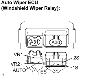 |
Disconnect the connector from the auto wiper ECU.
Measure the resistance according to the value(s) in the table below.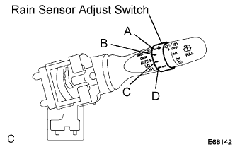
- Standard resistance:
Tester Connection
Condition
Specified Condition
1S - ES
Windshield wiper switch MIST position
Below 1 Ω
AUTO - Body ground
Windshield wiper switch AUTO position
Below 1 Ω
1S - ES
Windshield wiper switch LO position
Below 1 Ω
2S - ES
Windshield wiper switch HI position
Below 1 Ω
VR2 - VR1
Rain sensor adjust switch "A" position
Below 1 Ω
VR2 - VR1
Rain sensor adjust switch "B" position
405 to 493 Ω
VR2 - VR1
Rain sensor adjust switch "C" position
1,400 to 1,700 Ω
VR2 - VR1
Rain sensor adjust switch "D" position
2,200 to 3,200 Ω
|
|
||||
| OK | |
|
| 4. INSPECT WINDSHIELD WIPER RELAY ASSEMBLY |
Measure the voltage according to the value(s) in the table below.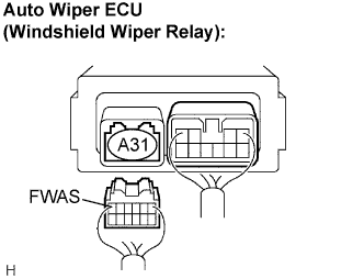
- Standard voltage:
Tester Connection
Condition
Specified Condition
FWAS - Body ground
Ignition switch ON
10 to 14 V
|
|
||||
| OK | ||
|
||
| ||
| 5. INSPECT WINDSHIELD WASHER MOTOR AND PUMP ASSEMBLY |
Inspect the front washer motor.
|
|
||||
| OK | ||
|
||
| ||