INSTALLATION
Removal / installation
| 1. INSTALL EXTENSION WIRE ASSEMBLY |

Install the wire harness clamp bracket with the bolt to the rear traction w/ transaxle motor.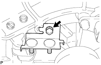

- Torque:
- 5.5 N*m{ 56 kgf*cm , 49 in.*lbf }
Install the wire harness clamp bracket and ground wire to the rear traction w/ transaxle motor with the bolt and nut.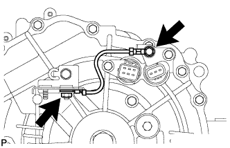
- Torque:
- 5.5 N*m{ 56 kgf*cm , 49 in.*lbf }
Install the extension wire with the 3 bolts to the rear traction w/ transaxle motor.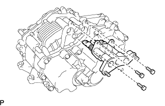
- CAUTION:
- Be sure to securely insert the extension wire assembly in to the rear traction motor.
- Torque:
- 10 N*m{ 102 kgf*cm , 7 ft.*lbf }
| 2. INSTALL FRONT DIFFERENTIAL SUPPORT ASSEMBLY |
Install the front differential support assembly with the 2 bolts to the rear traction w/ transaxle motor.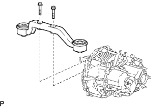
- Torque:
- 80 N*m{ 816 kgf*cm , 59 ft.*lbf }
| 3. INSTALL REAR TRACTION W/ TRANSAXLE MOTOR ASSEMBLY |
Place the lower stopper, differential support assembly FR w/ rear traction motor, and upper stopper in this order. Install them to the rear suspension member with the 4 bolts.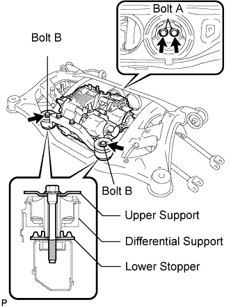
- Torque:
- Bolt A:
- 95 N*m{ 969 kgf*cm , 70 ft.*lbf }
- Bolt B:
- 103 N*m{ 1,050 kgf*cm , 76 ft.*lbf }
| 4. INSTALL REAR SUSPENSION MEMBER SUB-ASSEMBLY |
Slowly jack up the vehicle and install the rear suspension member w/ rear traction motor to the vehicle.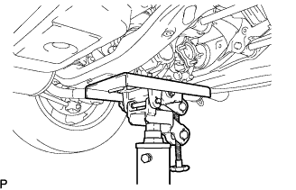
Install the rear suspension member to the vehicle with the 2 bolts and 4 nuts.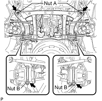
- Torque:
- Nut A:
- 115 N*m{ 1,173 kgf*cm , 85 ft.*lbf }
- Nut B:
- 181 N*m{ 1,846 kgf*cm , 134 ft.*lbf }
- NOTICE:
- When tightening the bolts B and nuts on the rear side, be sure to hold the bolt B and turn the nut.
| 5. CONNECT NO.3 WIRE FRAME |
Wear insulated gloves. Install the frame wire No.3 to the rear traction motor with the 2 nuts.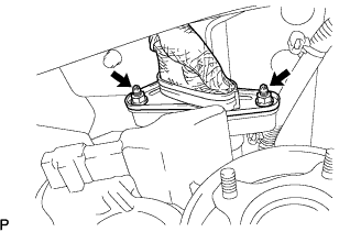
- Torque:
- 15 N*m{ 153 kgf*cm , 11 ft.*lbf }
Install the wire harness clamp to the vehicle with the nut.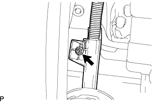
- Torque:
- 8.5 N*m{ 87 kgf*cm , 75 in.*lbf }
Install the ground cable to the rear traction motor with the nut.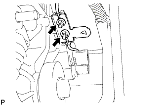
- Torque:
- 5.5 N*m{ 56 kgf*cm , 49 in.*lbf }
Connect the 2 connectors and clamp to the rear traction motor.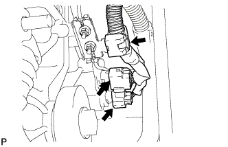
| 6. CONNECT PARKING BRAKE CABLE ASSEMBLY NO.3 |
Install the parking brake No.3 cable assembly with the 2 nuts.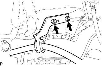
- Torque:
- 6.0 N*m{ 61 kgf*cm , 53 in.*lbf }
| 7. CONNECT PARKING BRAKE CABLE ASSEMBLY NO.2 |
- HINT:
- Install the RH side by following the same procedures as for the LH side.
| 8. INSTALL REAR DRIVE SHAFT ASSEMBLY LH |
Align the matchmarks.
Install the rear drive shaft assembly with the 4 nuts and washers.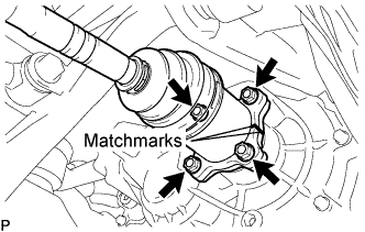
- Torque:
- 56 N*m{ 571 kgf*cm , 41 ft.*lbf }
| 9. INSTALL REAR DRIVE SHAFT ASSEMBLY RH |
- HINT:
- Install the RH side by following the same procedures as for the LH side.
| 10. TEMPORARILY TIGHTEN REAR SUSPENSION ARM ASSEMBLY NO.2 LH |
Jack up the rear axle carrier, placing a wooden block to avoid damage.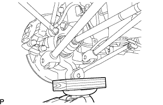
Temporarily tighten the rear suspension arm assembly No.2 with the bolt and nut.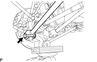
- HINT:
- Insert the bolt from the rear side of the vehicle and lightly tighten the bolt.
| 11. TEMPORARILY TIGHTEN REAR SUSPENSION ARM ASSEMBLY NO.2 RH |
- HINT:
- Install the RH side by following the same procedures as for the LH side.
| 12. TEMPORARILY TIGHTEN REAR SUSPENSION ARM ASSEMBLY NO.1 LH |
Temporarily tighten the rear suspension arm assembly No.1 with the bolt and nut.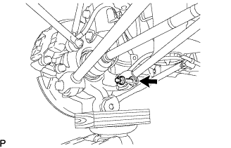
- HINT:
- Insert the bolt from the front side of the vehicle and lightly tighten the bolt.
| 13. TEMPORARILY TIGHTEN REAR SUSPENSION ARM ASSEMBLY NO.1 RH |
- HINT:
- Install the RH side by following the same procedures as for the LH side.
| 14. TEMPORARILY TIGHTEN REAR STRUT ROD ASSEMBLY |
Temporarily tighten the strut rod assembly rear with the bolt and nut.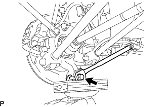
- HINT:
- Insert the bolt from the inside of the vehicle and lightly tighten the bolt.
| 15. STABILIZE SUSPENSION |
Jack up the rear axle carrier, placing a wooden block to avoid damage. Apply load to the suspension so that the rear drive shaft assembly is horizontally positioned.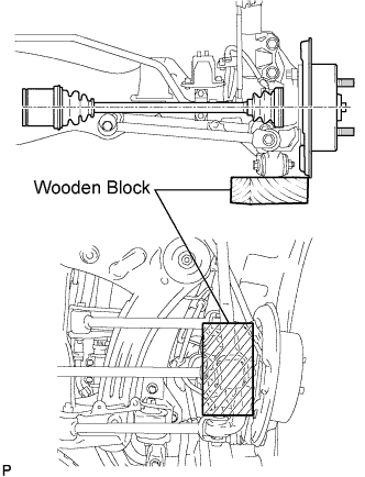
| 16. FULLY TIGHTEN REAR SUSPENSION ARM ASSEMBLY NO.2 LH |
Fully tighten the bolt.
- Torque:
- 112 N*m{ 1,140 kgf*cm , 83 ft.*lbf }
- NOTICE:
- Turn the bolt while holding the nut.
| 17. FULLY TIGHTEN REAR SUSPENSION ARM ASSEMBLY NO.2 RH |
- HINT:
- Install the RH side by following the same procedures as for the LH side.
| 18. FULLY TIGHTEN REAR SUSPENSION ARM ASSEMBLY NO.1 LH |
Fully tighten the bolt.
- Torque:
- 112 N*m{ 1,140 kgf*cm , 83 ft.*lbf }
- NOTICE:
- Turn the bolt while holding the nut.
| 19. FULLY TIGHTEN REAR SUSPENSION ARM ASSEMBLY NO.1 RH |
- HINT:
- Install the RH side by following the same procedures as for the LH side.
| 20. FULLY TIGHTEN REAR STRUT ROD ASSEMBLY |
Fully tighten the bolt.
- Torque:
- 80 N*m{ 816 kgf*cm , 59 ft.*lbf }
- NOTICE:
- Turn the bolt while holding the nut.
| 21. CONNECT HEIGHT CONTROL SENSOR |
Install the height control sensor with the 2 bolts.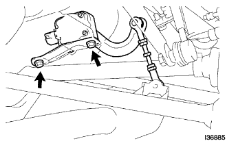
- Torque:
- 7.8 N*m{ 80 kgf*cm , 69 in.*lbf }
Install the height control sensor link with the "torx" nut.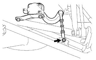
- Torque:
- 5.4 N*m{ 55 kgf*cm , 48 in.*lbf }
Connect the connector.
| 22. INSTALL REAR AXLE SHAFT LH NUT |
Using a socket wrench (30mm), install a new rear axle shaft nut.
- Torque:
- 294 N*m{ 3,000 kgf*cm , 217 ft.*lbf }
Using a chisel and hammer, stake the rear axle shaft nut.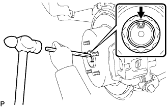
| 23. INSTALL REAR AXLE SHAFT RH NUT |
- HINT:
- Install the RH side by following the same procedures as for the LH side.
| 24. INSPECT AND ADJUST REAR WHEEL ALIGNMENT |
| 25. INSTALL EXHAUST PIPE ASSEMBLY |
| 26. INSTALL POWER STEERING ECU BRACKET |
Install the power steering ECU bracket with the bolt to the w/ converter inverter assembly.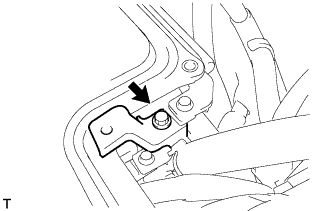
- Torque:
- 8.0 N*m{ 82 kgf*cm , 71 in.*lbf }
| 27. CONNECT INVERTER RESERVE TANK SUB-ASSEMBLY |
Connect the 2 water hoses with the 2 clamps to the inverter reserve tank sub-assembly.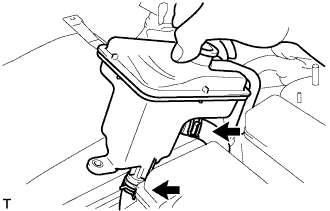
Install the inverter reserve tank with the 2 bolts to the w/ converter inverter assembly.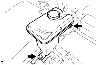
- Torque:
- 10 N*m{ 102 kgf*cm , 7 ft.*lbf }
| 28. INSTALL POWER STEERING ECU ASSEMBLY |
Install the power steering ECU assembly with the 2 bolts.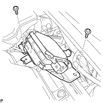
- Torque:
- 8.0 N*m{ 82 kgf*cm , 71 in.*lbf }
Connect the 2 wire harness clamps to the power steering ECU assembly.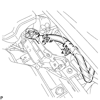
Connect the 2 power steering ECU assembly connectors and securely lock the connectors.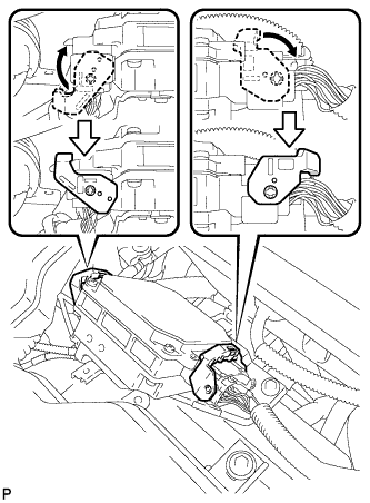
Install the ground cable terminal to the power steering ECU assembly with the bolt.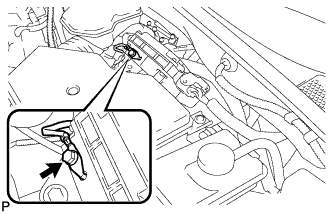
- Torque:
- 6.0 N*m{ 61 kgf*cm , 53 in.*lbf }
| 29. INSTALL INVERTER BRACKET NO.5 |
Install the inverter bracket No.5 with the bolt.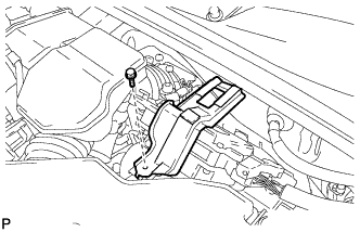
- Torque:
- 10 N*m{ 102 kgf*cm , 7 ft.*lbf }
| 30. INSTALL REAR WHEELS |
| 31. CONNECT CABLE TO NEGATIVE BATTERY TERMINAL |
| 32. CHECK HIGH VOLTAGE CABLE CONNECTION |
- NOTICE:
- Be sure to wear insulated gloves and protective goggles.
Make sure that the frame wire No.3 is securely installed with the nuts.
- NOTICE:
- Do not install the frame wire No.3 at an angle.
- Be sure to tighten the nuts securely.
- Do not install the frame wire No.3 at an angle.
| 33. INSTALL SERVICE PLUG GRIP |
- NOTICE:
- Before connecting the service plug, check that no parts and tools remain and that the high voltage terminals and connectors are connected securely.
Wear insulation gloves, then insert the service plug.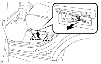
Push down on the grip to lock.
Close the battery service hole cover.
- NOTICE:
- Check that the 2 battery service hole cover clips are securely connected to the battery carrier bracket (click sound).
| 34. INSTALL ENGINE ROOM SIDE COVER LH |
Fit the clips and install the engine room side LH cover.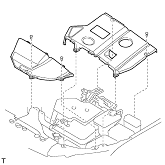
| 35. ADD AND INSPECT HYBRID TRANSAXLE FLUID |
Check that the oil surface is within 5 mm (0.20 in.) from the lowest position of the inner surface of the transaxle filler plug opening.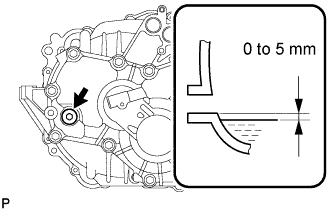
- Transaxle fluid quantity:
- 1.8 L (1.9 US qts, 1.6 Imp. qts)
- NOTICE:
- Stop the vehicle on a flat road.
- Recheck the transaxle oil level after driving when exchanging oil.
- Insufficient or excessive amounts of transaxle oil may be the cause of some trouble.
- Stop the vehicle on a flat road.
Check for leaks if the quantity of oil is low.
Using a socket hexagon wrench 10 mm, install the filler plug and a new gasket.
- Torque:
- 39 N*m{ 398 kgf*cm , 29 ft.*lbf }
| 36. INSPECT EXHAUST GAS LEAK |
| 37. HEADLIGHT AIM ONLY |
| 38. PERFORM INITIALIZATION |