REMOVAL
Removal / installation
| 1. PRECAUTION |

| 2. DISCONNECT CABLE FROM NEGATIVE BATTERY TERMINAL |
| 3. REMOVE SERVICE PLUG GRIP |
- CAUTION:
- Remove the service plug to interrupt a high voltage circuit at the time of the check.
- Keep the removed service plug in your pocket to prevent other technicians from reconnecting it while you are servicing the vehicle.
- All the high voltage wiring connectors are colored in orange.
- Remove the service plug to interrupt a high voltage circuit at the time of the check.
Remove the 2 clips, then open the battery service hole cover.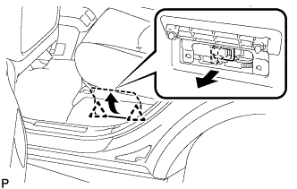

Wear insulation glove, and remove the service plug grip, after sliding up the lever of the service plug grip.
- CAUTION:
- Keep the removed service plug in your pocket to prevent other technicians from reconnecting it while you are servicing the vehicle.
- After removing the service plug grip, do not touch the high voltage connectors and terminals for 5 minutes.
- Keep the removed service plug in your pocket to prevent other technicians from reconnecting it while you are servicing the vehicle.
- NOTICE:
- After removing the service plug grip, do not operate the ignition switch as it may damage the hybrid vehicle control ECU.
| 4. REMOVE ENGINE ROOM SIDE COVER LH |
Using a clip remover, remove the engine room side cover.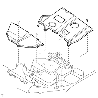
| 5. REMOVE INVERTER BRACKET NO.5 |
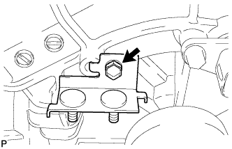
Remove the bolt and inverter bracket No.5.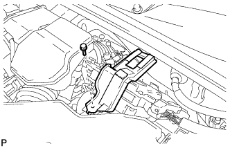
| 6. REMOVE POWER STEERING ECU ASSEMBLY |
Remove the bolt and ground cable terminal from the power steering ECU assembly.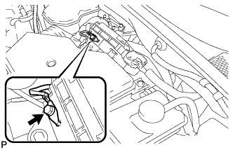
Release the locks of the 2 power steering ECU assembly connectors and disconnect the connectors.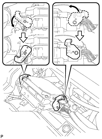
Separate the 2 wire harness clamps from the power steering ECU assembly.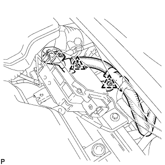
Remove the 2 bolts and the power steering ECU assembly.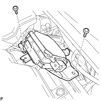
| 7. SEPARATE INVERTER RESERVE TANK SUB-ASSEMBLY |
Remove the 2 bolts and inverter reserve tank sub-assembly.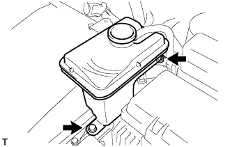
| 8. REMOVE POWER STEERING ECU BRACKET |
Remove the bolt, and disconnect the power steering ECU bracket.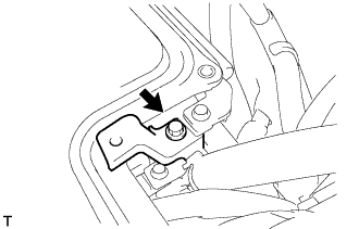
| 9. REMOVE INVERTER COVER |
Remove the bolt and interlock bracket.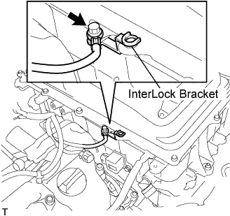
Insulate the removed terminal with insulating tape.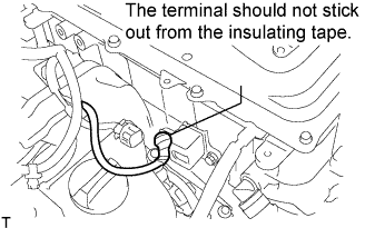
- NOTICE:
- Make sure that the terminal does not stick out from the insulating tape.
Remove the 12 bolts and inverter cover.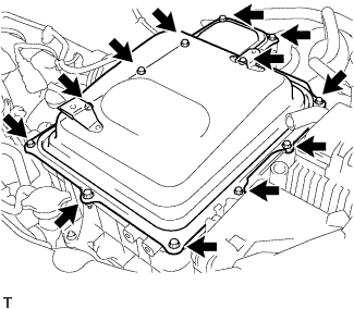
| 10. VERIFY THAT VOLTAGE OF W/ CONVERTER INVERTER ASSEMBLY IS 0V |
- CAUTION:
- Wear insulating gloves.
- NOTICE:
- Make sure that the inverter converter is temporarily installed before working on the converter inverter assembly. (Click here)
- Do not allow any foreign objects or waterdrops to enter the w/ converter inverter assembly.
- Make sure that the inverter converter is temporarily installed before working on the converter inverter assembly. (Click here)
Using the voltmeter, measure the voltage between the terminals of the 2 phase connectors (N-P).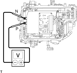
- Standard voltage:
- 0 V
- HINT:
- Use measuring range of DC 750 V or more on the voltmeter.
| 11. INSTALL INVERTER COVER |
Temporarily install the inverter cover with the 2 bolts to prevent any foreign objects or waterdrops from entering the w/ converter inverter assembly.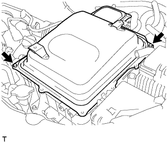
| 12. DRAIN HYBRID TRANSAXLE FLUID |
Using a socket hexagon wrench 10 mm, remove the filler plug and gasket.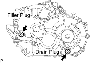
Using a socket hexagon wrench 10 mm, remove the drain plug and gasket.
Using a socket hexagon wrench 10 mm, install the drain plug and a new gasket.
- Torque:
- 39 N*m{ 398 kgf*cm , 29 ft.*lbf }
| 13. REMOVE REAR WHEELS |
| 14. REMOVE EXHAUST PIPE ASSEMBLY |
| 15. REMOVE REAR AXLE SHAFT LH NUT |
Using SST and a hammer, release the staked part of the axle shaft nut.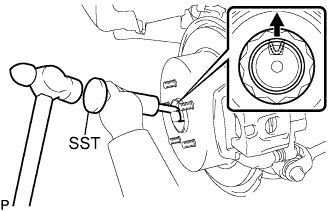
- SST
- 09930-00010
- NOTICE:
- Loosen the staked part of the nut completely, otherwise the screw of the drive shaft may be damaged.
While applying the brakes, remove the axle shaft nut.
| 16. REMOVE REAR AXLE SHAFT RH NUT |
- HINT:
- Removal procedure of the RH side is the same as that of the LH side.
| 17. DISCONNECT HEIGHT CONTROL SENSOR |
Disconnect the connector.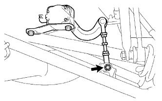
Remove the "torx" nut and separate the height control sensor link.
Remove the 2 bolts and height control sensor.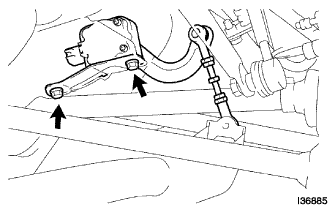
| 18. SEPARATE REAR STRUT ROD ASSEMBLY |
Support the rear axle carrier with a wooden block placed between the jack and axle carrier.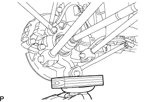
Remove the bolt, nut and strut rod assembly rear.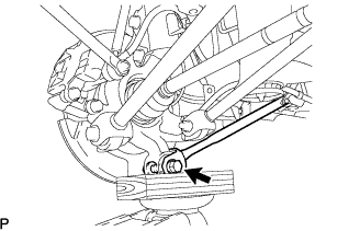
- NOTICE:
- Hold the nut to turn the bolt.
| 19. SEPARATE REAR SUSPENSION ARM ASSEMBLY NO.1 LH |
Remove the bolt and nut, and separate the rear suspension arm assembly No.1.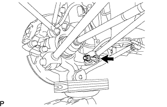
- NOTICE:
- Hold the nut to turn the bolt.
| 20. SEPARATE REAR SUSPENSION ARM ASSEMBLY NO.1 RH |
- HINT:
- Removal procedure of the RH side is the same as that of the LH side.
| 21. SEPARATE REAR SUSPENSION ARM ASSEMBLY NO.2 LH |
Remove the bolt and nut, and separate the rear suspension arm assembly No.2.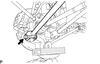
- NOTICE:
- Hold the nut to turn the bolt.
| 22. SEPARATE REAR SUSPENSION ARM ASSEMBLY NO.2 RH |
- HINT:
- Removal procedure of the RH side is the same as that of the LH side.
| 23. REMOVE REAR DRIVE SHAFT ASSEMBLY LH |
Put matchmarks on the rear drive shaft assembly and differential side gear shaft.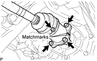
Remove the 4 nuts, washers and rear drive shaft assembly.
| 24. REMOVE REAR DRIVE SHAFT ASSEMBLY RH |
- HINT:
- Removal procedure of the RH side is the same as that of the LH side.
| 25. SEPARATE PARKING BRAKE CABLE ASSEMBLY NO.3 |
Remove the 2 nuts, and separate the parking brake cable assembly No.3.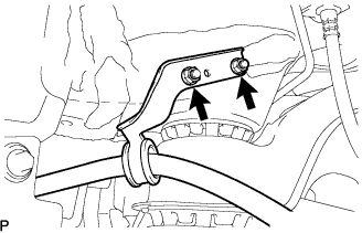
| 26. SEPARATE PARKING BRAKE CABLE ASSEMBLY NO.2 |
- HINT:
- Removal procedure of the RH side is the same as that of the LH side.
| 27. SEPARATE NO.3 WIRE FRAME |
- NOTICE:
- Wear insulating gloves.
Disconnect the 2 connectors and clamp.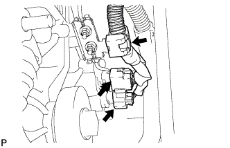
Remove the 2 nuts, and separate the ground cable.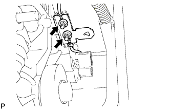
Remove the nut, and separate the wire harness clamp.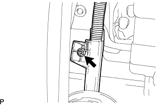
Wear the insulated gloves. Remove the 2 nuts, and separate the frame wire No.3 from the rear traction motor.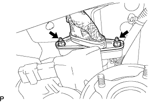
| 28. REMOVE REAR SUSPENSION MEMBER SUB-ASSEMBLY |
Support the rear suspension member with a jack.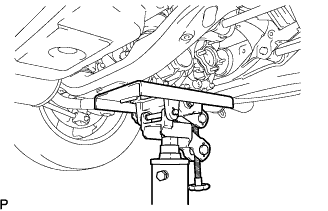
- HINT:
- Remove the rear suspension member together with the rear traction motor.
Remove the 2 bolts and 4 nuts, and separate the rear suspension member.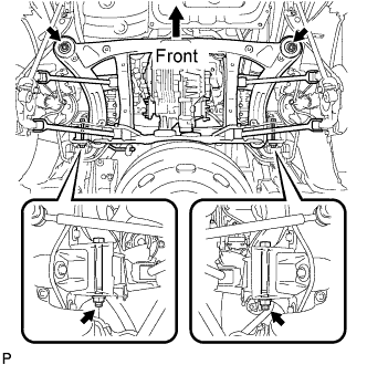
- NOTICE:
- When removing the bolts and nuts on the rear side, be sure to hold the bolt.
| 29. REMOVE REAR TRACTION W/ TRANSAXLE MOTOR ASSEMBLY |
Remove the 4 bolts, rear traction w/ transaxle motor assembly.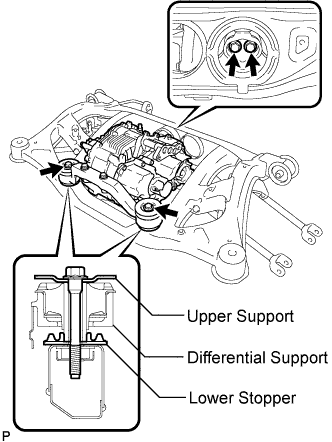
| 30. REMOVE FRONT DIFFERENTIAL SUPPORT ASSEMBLY |
Remove the 2 bolts and front differential support assembly.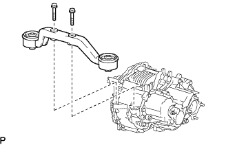
| 31. REMOVE EXTENSION WIRE ASSEMBLY |
Remove the 3 bolts and extension wire assembly.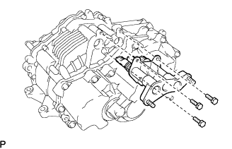
Remove the bolt, nut, ground cable, and wire harness clamp bracket.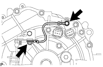
Remove the bolt and wire harness clamp bracket.