INSTALLATION
Removal / installation
| 1. INSTALL FUEL TANK CUSHION |

Install 8 new fuel tank cushions to the fuel tank.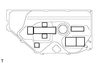

| 2. INSTALL CLAMP |
Install the clamp to the fuel tank.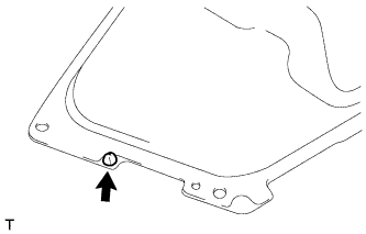
Install the 2 fuel tube clamps of the fuel tank main tube to the fuel tank.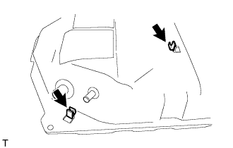
| 3. INSTALL FUEL TANK MAIN TUBE SUB-ASSEMBLY |
Install the fuel tank main tube to the clamp.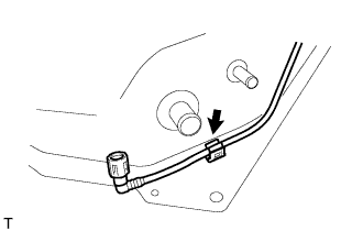
| 4. INSTALL FUEL TANK TO CANISTER TUBE SUB-ASSEMBLY |
Connect the fuel tank to canister tube sub-assembly.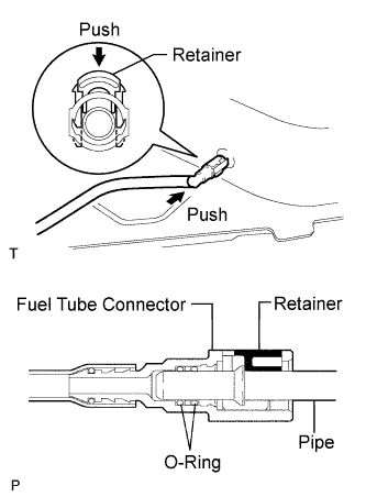
Push in the fuel tube connector to the pipe and push down the retainer so that the claws engage.
- NOTICE:
- Check for damage or foreign objects on the connected part of the fuel pipe.
- After connecting, check that the fuel tube connector and the pipe are securely connected by pulling on them.
- Check for damage or foreign objects on the connected part of the fuel pipe.
Install the fuel tank to canister tube to the fuel tank.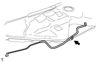
| 5. INSTALL FUEL TANK WIRE |
Install the fuel tank wire.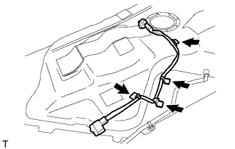
| 6. INSTALL FUEL PUMP AND GAUGE WITH SUCTION TUBE |
Install a new gasket on the fuel pump assembly.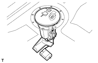
Install the fuel pump assembly.
Install the fuel tank vent tube set plate by aligning it with the cutout on the fuel pump assembly.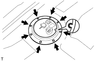
Install the fuel tank vent tube set plate with the 8 bolts.
- Torque:
- 6.0 N*m{ 61 kgf*cm , 53 in.*lbf }
Connect the fuel tank main tube with the tube joint clip and clamp.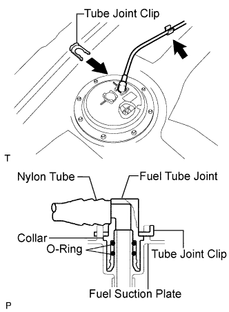
- NOTICE:
- Check that there is no scratches or foreign objects on the connecting part.
- Check that there is no scratches or foreign objects on the connecting part.
- Check that the fuel tube joint is inserted securely.
- Check that the fuel tube joint is inserted securely.
- Check that the tube joint clip is on the collar of the fuel tube joint.
- Check that the tube joint clip is on the collar of the fuel tube joint.
- After installing the tube joint clip, check that the fuel tube joint cannot be pulled off.
- After installing the tube joint clip, check that the fuel tube joint cannot be pulled off.
Connect the fuel tank wire connector.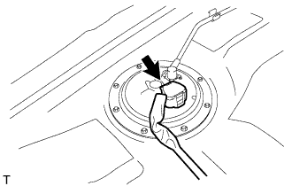
| 7. INSTALL FUEL TANK ASSEMBLY |
Operate the transmission jack, and install the fuel tank to the vehicle.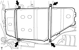
Install the 2 fuel tank bands with the 4 bolts.
- Torque:
- 39 N*m{ 400 kgf*cm , 29 ft.*lbf }
| 8. CONNECT FUEL TANK TO FILLER PIPE HOSE |
Connect the fuel tank to filler pipe hose with the hose clamp.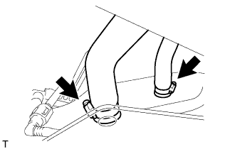
Connect the fuel tank breather hose with the hose clamp.
| 9. CONNECT FUEL TANK MAIN TUBE SUB-ASSEMBLY |
Connect the fuel tank main tube sub-assembly.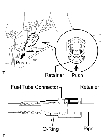
Push in the fuel tube connector to the pipe and push up the retainer to engage the claws.
- NOTICE:
- Check for damage or foreign objects on the connected part.
- After connecting, check that the fuel tube connector and the pipe are securely connected by pulling on them.
- Check for damage or foreign objects on the connected part.
| 10. CONNECT FUEL TANK TO CANISTER TUBE SUB-ASSEMBLY |
Install the fuel tank to canister tube sub-assembly to the clamp.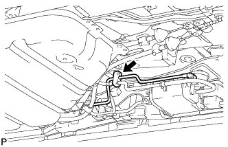
Connect the fuel tank to canister tube sub-assembly.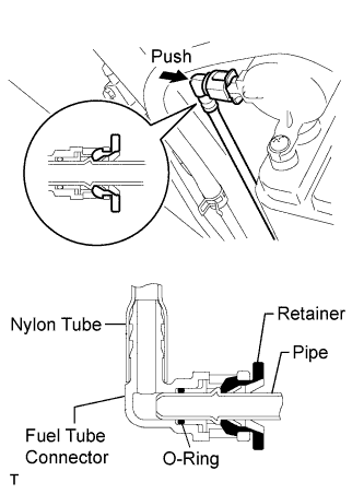
Push the fuel tube connector into the pipe until the fuel tube connector makes a "click" sound.
- NOTICE:
- Check for any damage or foreign objects on the connected part.
- After connecting, check that the fuel tube connector and the pipe are securely connected by trying to pull them apart.
- Check for any damage or foreign objects on the connected part.
| 11. INSTALL CHARCOAL CANISTER PROTECTOR |
Install the charcoal canister protector with the 3 bolts.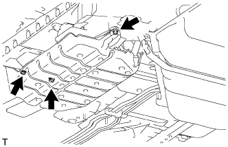
- Torque:
- 5.4 N*m{ 55 kgf*cm , 48 in.*lbf }
| 12. CONNECT FUEL TANK WIRE |
Connect the fuel tank wire connector, and install it to the bracket.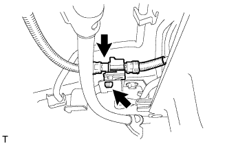
| 13. INSTALL PARKING BRAKE CABLE ASSEMBLY NO.3 |
Install the parking brake cable assembly No.3 with the nut.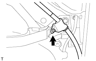
- Torque:
- 6.0 N*m{ 61 kgf*cm , 53 in.*lbf }
| 14. INSTALL FUEL TANK PROTECTOR SUB-ASSEMBLY NO.1 |
Install the fuel tank protector sub-assembly No.1 with the screw and the 4 grommets.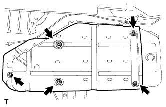
| 15. INSTALL FRONT FLOOR HEAT INSULATOR NO.3 |
Install the front floor heat insulator No.3 with the 5 nuts.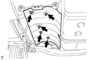
- Torque:
- 4.9 N*m{ 50 kgf*cm , 43 in.*lbf }
| 16. INSTALL EXHAUST PIPE ASSEMBLY CENTER |
| 17. CONNECT CABLE TO NEGATIVE BATTERY TERMINAL |
| 18. ADD FUEL |
| 19. CHECK FOR FUEL LEAKS |
Connect the intelligent tester to the DLC3.
Turn the ignition switch to the ON position and turn the intelligent tester on.
- NOTICE:
- Do not start the engine.
Select the Active Test mode on the intelligent tester to operate the fuel pump.
- HINT:
- Refer to the intelligent tester operator's manual for further details.
Check that there are no fuel leaks anywhere in the fuel system after performing maintenance.
| 20. CHECK FOR EXHAUST GAS LEAKS |
| 21. PERFORM INITIALIZATION |