P3107-214
Diagnostic trouble codes
DESCRIPTION
Refer to the description for DTC P3107-213. (Click here)| DTC No. |
INF Code |
DTC Detection Condition |
Trouble Area |
| P3107 |
214 |
Open or +B short circuit in communication circuit |
|
WIRING DIAGRAM
Refer to the wiring diagram for DTC P3107-213. (Click here)INSPECTION PROCEDURE
| 1. INSPECT HYBRID VEHICLE CONTROL ECU |

Connect the intelligent tester to the HV control ECU terminals specified in the table below and check the waveform.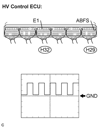

Item
Contents
Terminal
ABFS (H29-8) - E1 (H32-5)
Equipment Setting
5 V/DIV, 500 ms/DIV
Condition
READY-on state
- OK:
- The waveform appears as shown in the illustration.
|
|
||||

| OK | |
 |
| 2. CHECK FOR INTERMITTENT PROBLEMS |
| NEXT | |
|
| 3. CHECK HYBRID VEHICLE CONTROL ECU |
Turn the ignition switch off.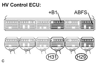
Disconnect the all connectors from the HV control ECU.
Measure the resistance according to the value(s) in the table below.
- Standard Resistance:
Tester Connection
Specified Condition
ABFS (H29-8) - +B (H31-2)
13k to 17 kΩ
at 20°C (68°F)
|
|
||||

| OK | |
|
| 4. CHECK HARNESS AND CONNECTOR (HV CONTROL ECU - AIRBAG SENSOR ASSEMBLY CENTER) |
Turn the ignition switch off.
Connect the H29 connector to the HV control ECU.
Disconnect the A24 connector from the airbag sensor assembly center.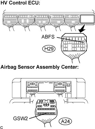
Measure the voltage according to the value(s) in the table below when the ignition switch is in the ON position.
- Standard Voltage:
Tester Connection
Specified Condition
ABFS (H29-8) - Body ground
Below 1 V
Turn the ignition switch off.
Measure the resistance according to the value(s) in the table below.
- Standard Resistance:
Tester Connection
Standard:
ABFS (H29-8) - GSW2 (A24-25)
Below 1 Ω
|
|
||||
| OK | ||
 |
||
| ||