P0A79-692
Diagnostic trouble codes
DESCRIPTION
Refer to the description of the inverter. (Click here)If the rear motor inverter circuit is opened or shorted, or if the circuit overheats, the information is transmitted from the inverter to the RFIV terminal of the MG ECU via the rear motor inverter fail signal line.
| DTC No. |
INF Code |
DTC Detection Condition |
Trouble Area |
| P0A79 |
692 |
Rear Motor inverter fail signal detection (overheating) |
|
MONITOR DESCRIPTION
If the rear motor inverter overheats, it transmits an inverter fail signal to the MG ECU. Upon receiving this signal, the HV control ECU illuminates the MIL and sets a DTC.INSPECTION PROCEDURE
- CAUTION:
- Before inspecting the high-voltage system, take safety precautions to prevent electrical shocks, such as wearing insulated gloves and removing the service plug grip. After removing the service plug grip, put it in your pocket to prevent other technicians from reconnecting it while you are working on the high-voltage system.
- After disconnecting the service plug grip, wait for at least 5 minutes before touching any of the high-voltage connectors or terminals.
- Before inspecting the high-voltage system, take safety precautions to prevent electrical shocks, such as wearing insulated gloves and removing the service plug grip. After removing the service plug grip, put it in your pocket to prevent other technicians from reconnecting it while you are working on the high-voltage system.
- HINT:
- At least 5 minutes is required to discharge the high-voltage capacitor inside the w/ converter inverter assembly.
| 1. READ OUTPUT DTC (HV) |

Connect the intelligent tester to the DLC3.
Turn the ignition switch to the ON position.
Select the following menu items: Powertrain / Hybrid Control / DTC.
Read output DTCs. (Click here)
- Result:
- The DTCs shown in the table below are output:
DTC No.
Relevant Diagnosis
P0A1D
HV ECU circuit malfunction
P0A2B, P0A2C, P0A2D
Motor temperature sensor circuit
P0A37, P0A38, P0A39
Generator temperature sensor circuit
P0A3F, P0A40, P0A41
Motor resolver circuit
P0A4B, P0A4C, P0A4D
Generator resolver circuit
P0A60, P0A63
Motor current sensor circuit
P0A72, P0A75
Generator current sensor circuit
P0A78
Motor inverter function malfunction
P0A7A
Generator inverter function malfunction
P0A90
Motor function malfunction
P0A92
Generator function malfunction
P0A93
Inverter cooling system
P0A94
Boost converter circuit
P0AA1, P0AA2, P0AA4, P0AA5
System main relay circuit
P3000, P3003, P0AA6, P3110
High-voltage system
P0AEE, P0AEF, P0AF0
Motor inverter temperature sensor circuit
P3221
Generator inverter temperature sensor circuit
P3226
Boost converter temperature sensor circuit
P0A05
Water pump w/ Motor malfunction
P0A79 (Except for 692, 812, 813, and 814)
Rear motor inverter function malfunction
P0AF3, P0AF4, P0AF5
Rear motor temperature sensor malfunction
P0A45, P0A46, P0A47
Rear motor resolver malfunction
P0A69, P0A6C, P0A55
Rear motor current sensor circuit
P0A1A, P0A1B, P0A1C
MG ECU malfunction
- NOTICE:
- If P0A79-692 is output, repair the malfunctioning area indicated by the DTC, or replace the w/ converter inverter assembly after repairing the malfunctioning area.
- HINT:
- Turning the ignition switch to the ON position with the service plug grip and inverter cover removed causes interlock switch system DTC P0A0D-350 to be output.
- P0A79-692 may be output due to a malfunction which causes the DTCs in the table above to be output. In this case, first troubleshoot the output DTCs in the table above. Then, perform a reproduction test to check that no DTCs are output.
- Turning the ignition switch to the ON position with the service plug grip and inverter cover removed causes interlock switch system DTC P0A0D-350 to be output.
|
|
||||

| NO | |
 |
| 2. CHECK QUANTITY OF HV COOLANT |
Check the inverter coolant level.
- OK:
- There is sufficient amount of coolant for the inverter.
|
|
||||
| OK | |
|
| 3. CHECK COOLANT HOSE |
Check if the hoses of the cooling system are not bent or clogged.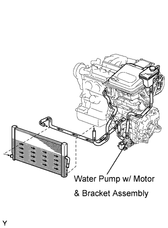

- OK:
- The hoses of the cooling system are not bent or clogged.
|
|
||||
| OK | |
|
| 4. CHECK CONNECTION CONDITION OF WATER PUMP CONNECTOR (LOOSENESS AND POOR CONTACT) |
Check the connection of the water pump w/ motor & bracket assembly connector.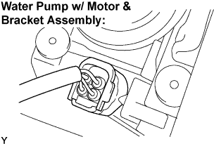
- OK:
- Connector is connected securely and there is no poor connection.
|
|
||||
| OK | |
|
| 5. PERFORM ACTIVE TEST BY INTELLIGENT TESTER (WATER PUMP) |
Connect the intelligent tester to the DLC3.
Turn the ignition switch to the ON position.
Select the following menu items: Powertrain / Hybrid Control / Active Test / Active Water Pump.
During the water pump active test, check operation of the water pump w/ motor & bracket assembly.
- Result:
- There are ripples in the reservoir tank coolant.
|
|
||||
| OK | |
|
| 6. PERFORM ACTIVE TEST BY INTELLIGENT TESTER (COOLING FAN) |
Connect the intelligent tester to the DLC3.
Turn the ignition switch to the ON position.
Select the following menu items: Powertrain / Engine / Active Test / Cooling Fan.
Perform the cooling fan active test.
- OK:
- The electric cooling fan rotates.
|
|
||||
| OK | |
|
| 7. CHECK CONNECTION CONDITION OF HYBRID VEHICLE CONTROL ECU CONNECTOR (LOOSENESS AND POOR CONTACT) |
Check the connections of all HV control ECU connectors.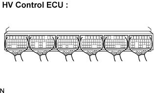
- OK:
- Connectors are connected securely and there is no poor connection.
|
|
||||
| OK | |
|
| 8. CHECK CONNECTION CONDITION OF MG ECU CONNECTOR (LOOSENESS AND POOR CONTACT) |
- CAUTION:
- Be sure to wear insulated gloves.
Turn the ignition switch off and remove the service plug grip. (Click here)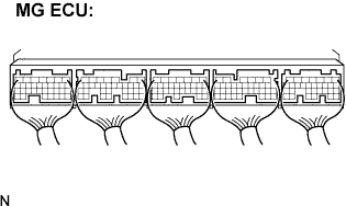
- NOTICE:
- Do not put the vehicle into the READY-on state with the service plug grip removed as this may cause a malfunction.
Remove the inverter cover. (Click here)
- NOTICE:
- Wrap the interlock round terminal for the inverter cover with vinyl tape to prevent it from shorting to ground.
- Prevent water in the reservoir tank from entering the inverter.
- Removing the inverter cover causes the MG ECU board to be exposed. Therefore, temporarily install the inverter cover for each area to be inspected.
- Wrap the interlock round terminal for the inverter cover with vinyl tape to prevent it from shorting to ground.
Check the connections of the MG ECU connectors.
- OK:
- Connectors are connected securely and there is no poor connection.
|
|
||||
| OK | |
|
| 9. INSPECT REAR TRACTION MOTOR W/TRANSAXLE ASSEMBLY |
- CAUTION:
- Be sure to wear insulated gloves.
Check that the service plug grip is removed.
Disconnect the three-phase AC cable of the Rear Motor from the inverter.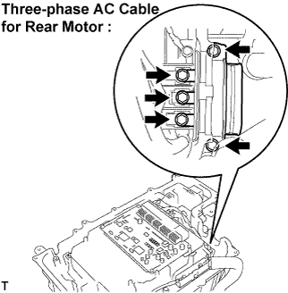
Using a milliohmmeter, measure the resistance according to the value(s) in the table below.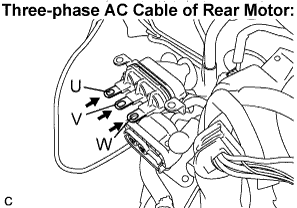
- Standard Resistance:
Tester Connection
Specified Condition
U - V
146 to 163 mΩ (20°C)
V - W
146 to 163 mΩ (20°C)
W - U
146 to 163 mΩ (20°C)
- NOTICE:
- If the Rear Motor temperature is too high, the resistance changes greatly. Therefore, measure the resistance at least 8 hours after the vehicle is stopped.
To correct the resistance varying depending on the temperature, use the following formula to calculate the resistance at 20°C.
- HINT:
- R20 = Rt / {1 + 0.00393 X (T - 20)}
- R20: Resistance at 20 °C (mΩ)
- Rt: Measured resistance (mΩ)
- T: Temperature when the resistance is measured (°C)
- R20 = Rt / {1 + 0.00393 X (T - 20)}
Calculate the difference between the maximum and minimum resistance.
- Standard resistance:
- Difference is 5 mΩ or less
Using a megohmmeter, measure the insulation resistance according to the value(s) in the table below.
- Standard Resistance:
Tester Connection
Specified Condition
U - Body ground and shielded wire ground
10 MΩ or higher
V - Body ground and shielded wire ground
10 MΩ or higher
W - Body ground and shielded wire ground
10 MΩ or higher
|
|
||||

| OK | |
|
| 10. CHECK HARNESS AND CONNECTOR (MG ECU - REAR MOTOR RESOLVER) |
- NOTICE:
- Be sure to wear insulated gloves.
Disconnect the I25 connector from the MG ECU.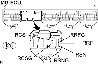
Measure the voltage according to the value(s) in the table below when the ignition switch is in the ON position.
- Standard Voltage:
Tester Connection
Specified Condition
RRF (I25-21) - Body ground
Below 1 V
RRFG (I25-22) - Body ground
Below 1 V
RSN (I25-29) - Body ground
Below 1 V
RSNG (I25-30) - Body ground
Below 1 V
RCS (I25-11) - Body ground
Below 1 V
RCSG (I25-23) - Body ground
Below 1 V
- NOTICE:
- Turning the ignition switch to the ON position with the MG ECU connectors disconnected causes other DTCs to be stored. Clear the DTCs after performing the inspection.
Turn the ignition switch off.
Measure the resistance according to the value(s) in the table below.
- Standard Resistance (Check for open):
Tester Connection
Specified Condition
RRF (I25-21) - RRFG (I25-22)
7.65 to 10.2 Ω
RSN (I25-29) - RSNG (I25-30)
12.6 to 16.8 Ω
RCS (I25-11) - RCSG (I25-23)
12.6 to 16.8 Ω
- Standard Resistance (Check for short):
Tester Connection
Specified Condition
RRF (I25-21) or RRFG (I25-22) - Body ground
10 kΩ or higher
RSN (I25-29) or RSNG (I25-30) - Body ground
10 kΩ or higher
RCS (I25-11) or RCSG (I25-23) - Body ground
10 kΩ or higher
|
|
||||
| NG | |
|
| 11. CHECK CONNECTION CONDITION OF REAR MOTOR RESOLVER CONNECTOR (LOOSENESS AND POOR CONTACT) |
Check the connections of the rear motor resolver connector.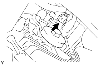
- OK:
- Connectors are connected securely and there is no poor connection.
|
|
||||
| OK | |
|
| 12. INSPECT REAR MOTOR RESOLVER |
Disconnect the M11 rear motor resolver connector.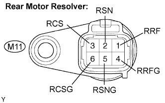
Measure the resistance according to the value(s) in the table below.
- Standard Resistance:
Tester Connection
Specified Condition
RRF (M11-1) - RRFG (M11-4)
7.65 to 10.2 Ω
RSN (M11-2) - RSNG (M11-5)
12.6 to 16.8 Ω
RCS (M11-3) - RCSG (M11-6)
12.6 to 16.8 Ω
Using a megohmmeter, measure the insulation resistance according to the value(s) in the table below.
- Standard Resistance:
Tester Connection
Specified Condition
RRF (M11-1) - RSN (M11-2)
10 MΩ or higher
RRF (M11-1) - RCS (M11-3)
10 MΩ or higher
RSN (M11-2) - RCS (M11-3)
10 MΩ or higher
RRFG (M11-4) - RSNG (M11-5)
10 MΩ or higher
RRFG (M11-4) - RCSG (M11-6))
10 MΩ or higher
RSNG (M11-5) - RCSG (M11-6)
10 MΩ or higher
Each terminal listed above - Transaxle housing
10 MΩ or higher
|
|
||||
| OK | ||
 |
||
| ||
| 13. CHECK FRAME WIRE NO.3 (W/ CONVERTER INVERTER ASSEMBLY - REAR TRACTION MOTOR) |
- CAUTION:
- Be sure to wear insulated gloves.
Check the service plug grip is removed.
Remove the frame wire No.3 (three-phase AC cable for Rear Motor) from the rear traction motor w/ transaxle assembly.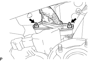
Using a megohmmeter, measure the insulation resistance according to the value(s) in the table below.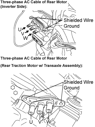
- Standard Resistance:
Tester Connection
Specified Condition
U - Body ground and shielded wire ground
10 MΩ or higher
V - Body ground and shielded wire ground
10 MΩ or higher
W - Body ground and shielded wire ground
10 MΩ or higher
- NOTICE:
- Wrap the three-phase AC cable terminals on the w/ converter inverter assembly side with protective tape to prevent the terminals from contacting the vehicle body.
Measure the resistance according to the value(s) in the table below.
- Standard Resistance:
Tester Connection
Specified Condition
U - U
Below 1 Ω
V - V
Below 1 Ω
W - W
Below 1 Ω
|
|
||||
| OK | |
|
| 14. INSPECT EXTENSION WIRE ASSEMBLY |
Remove the rear traction motor w/ transaxle assembly. (Click here)
Remove the extension wire assembly from the rear traction motor w/ transaxle assembly. (Click here)
Using a megohmmeter, measure the insulation resistance according to the value(s) in the table below.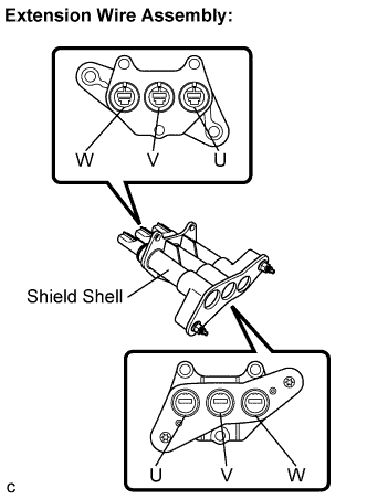
- Standard Resistance:
Tester Connection
Specified Condition
U - Shield shell
10 MΩ or higher
V - Shield shell
10 MΩ or higher
W - Shield shell
10 MΩ or higher
Measure the resistance according to the value(s) in the table below.
- Standard Resistance:
Tester Connection
Specified Condition
U - U
Below 1 Ω
V - V
Below 1 Ω
W - W
Below 1 Ω
|
|
||||
| OK | ||
|
||
| ||