INSTALLATION
Removal / installation
| 1. INSTALL INPUT SHAFT OIL SEAL |

Using SST and a hammer, drive in a new oil seal.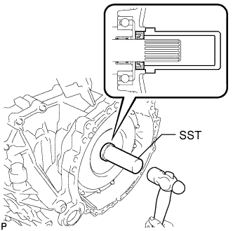

- SST
- 09388-40010
| 2. INSTALL HYBRID VEHICLE TRANSAXLE ASSEMBLY |
Make sure that the knock pins are installed on the engine.
Install the hybrid vehicle transaxle and the 8 bolts shown in the illustration to the engine.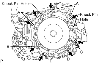
- Torque:
- Bolt A:
- 64 N*m{ 653 kgf*cm , 47 ft.*lbf }
- Torque:
- Bolt B:
- 46 N*m{ 469 kgf*cm , 34 ft.*lbf }
- Torque:
- Bolt C:
- 64 N*m{ 653 kgf*cm , 47 ft.*lbf }
- Torque:
- Bolt D:
- 37 N*m{ 377 kgf*cm , 27 ft.*lbf }
- NOTICE:
- Do not reuse bolt B.
- Do not forcibly pry out the hybrid vehicle transaxle assembly
- Do not apply the grease either to the spline or to the input shaft.
- Do not reuse bolt B.
Bolt
Installation direction
Diameter
Bolt length
A
From transaxle to engine
12 mm (0.47 in.)
55 mm (2.17 in.)
B
From engine to transaxle
10 mm (0.39 in.)
55 mm (2.17 in.)
C
From transaxle to engine
12 mm (0.47 in.)
55 mm (2.17 in.)
D
From engine to transaxle
10 mm (0.39 in.)
33 mm (1.30 in.)
| 3. INSTALL ENGINE MOUNTING BRACKET FRONT |
Install the engine mounting bracket front with the 3 bolts.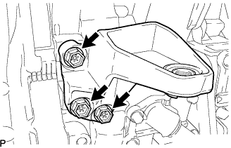
- Torque:
- 64 N*m{ 653 kgf*cm , 47 ft.*lbf }
| 4. INSTALL AUTOMATIC TRANSMISSION CASE COVER |
Install the case cover with the bolt and clip.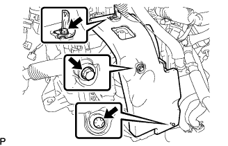
Install the wire harness bracket with the bolt.
- Torque:
- 8.4 N*m{ 86 kgf*cm , 74 in.*lbf }
| 5. CONNECT ENGINE WIRE |
Install the 4 wire harness brackets with the bolts.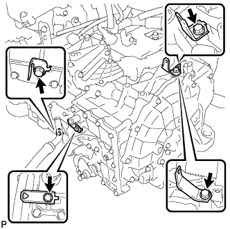
- Torque:
- 8.4 N*m{ 86 kgf*cm , 74 in.*lbf }
Connect the connector.
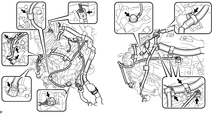
Connect the wire harnesses to the wire harness clamp.
Install the ground wire with the bolt.
- Torque:
- 8.4 N*m{ 86 kgf*cm , 74 in.*lbf }
| 6. INSTALL FLYWHEEL HOUSING UNDER COVER |
Install the flywheel housing under cover with the 2 bolts.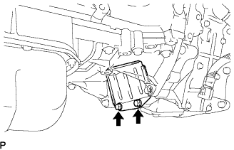
- Torque:
- 7.8 N*m{ 80 kgf*cm , 69 in.*lbf }
| 7. INSTALL FRONT DRIVE SHAFT ASSEMBLY LH |
Install a new drive shaft hole snap ring.
Coat the spline of the inboard joint shaft assembly with ATF.
Align the shaft splines and install the drive shaft assembly with a brass bar and a hammer.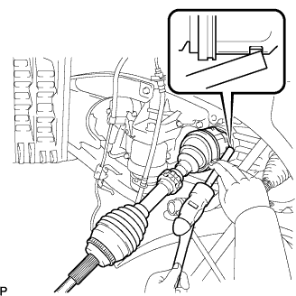
- NOTICE:
- Set the snap ring with the opening side facing down.
- Be careful not to damage the drive shaft dust cover, boot, or oil seal.
- Set the snap ring with the opening side facing down.
| 8. INSTALL FRONT DRIVE SHAFT ASSEMBLY RH |
Coat the spline of the inboard joint shaft assembly with ATF.
Align the shaft splines and install the drive shaft assembly.
- NOTICE:
- Be careful not to damage the drive shaft dust cover, boot, or oil seal.
Using pliers, install a new bearing bracket hole snap ring.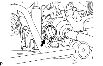
Install a new bolt to the drive shaft bearing bracket.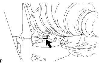
- Torque:
- 32 N*m{ 330 kgf*cm , 24 ft.*lbf }
| 9. INSTALL FRONT FRAME ASSEMBLY |
Install the engine mounting insulators RH and LH with the 2 nuts.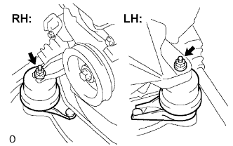
- Torque:
- 95 N*m{ 969 kgf*cm , 70 ft.*lbf }
Install the engine mounting insulator FR with the nut.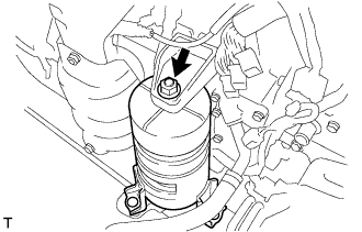
- Torque:
- 87 N*m{ 887 kgf*cm , 64 ft.*lbf }
Install the engine mounting insulator RR with the 2 bolts.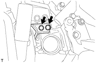
- Torque:
- 75 N*m{ 765 kgf*cm , 55 ft.*lbf }
| 10. INSTALL HV TRANSAXLE MASS DAMPER |
Install the bolt and transaxle mass damper.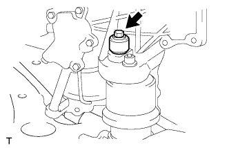
- Torque:
- 14 N*m{ 138 kgf*cm , 10 ft.*lbf }
| 11. INSTALL MANIFOLD STAY |
Temporarily install the manifold stay to the exhaust manifold and transaxle.
Fully tighten the 2 bolts.
- Torque:
- 34 N*m{ 347 kgf*cm , 25 ft.*lbf }
| 12. INSTALL ENGINE ASSEMBLY WITH TRANSAXLE |