P3190 Following conditions continue at a fixed engine RPM or a fixed length of time: Communication with HV ECU is...
Diagnostic trouble codes
DESCRIPTION
From the HV ECU, the ECM (Included in HV Control ECU) receives data such as power output required for the engine (required output), estimated torque produced by the engine (estimated torque), engine RPM of control target (target RPM), whether the engine is in start mode or not. Then, based on the required output and target RPM, the ECM (Included in HV Control ECU) calculates a target torque that is to be produced by the engine and compares it with the estimated torque. If the estimated torque is very low compared with the target torque, or the engine start mode continues for the specific duration calculated by water temperature, an abnormal condition is detected.| DTC No. |
DTC Detection Condition |
Trouble Area |
| P3190 |
Following conditions continue at a fixed engine RPM or a fixed length of time:
|
|
| P3191 |
Following conditions continue at a fixed engine RPM or a fixed length of time:
|
|
| P3193 |
Following conditions are met:
|
|
INSPECTION PROCEDURE
- HINT:
- Read freeze frame data using the intelligent tester or the OBD II scan tool. Freeze frame data records the engine condition when malfunction is detected. When troubleshooting, freeze frame data can help determine if the vehicle was running or stopped, if the engine was warmed up or not, if the air-fuel ratio was lean or rich, and other data from the time the malfunction occurred.
| 1. CHECK OTHER DTC OUTPUT (IN ADDITION TO DTC P3190, P3191 AND/OR P3193) |

Connect the intelligent tester to the DLC3.
Turn the ignition switch ON.
Turn the intelligent tester or the OBD II scan tool ON.
On the intelligent tester, select the item: Powertrain / Engine / DTC.
Read DTCs using the hand-held tester or the OBD II scan tool.
- Result:
Display (DTC output)
Proceed to
P3190, P3191 and/or P3193
A
P3190, P3191 and/or P3193, and other DTCs
B
- HINT:
- If any other codes besides P3190, P3191 and/or P3193 are output, perform troubleshooting for those DTCs first.
|
|
||||

| A | |
 |
| 2. CHECK SHORTAGE OF FUEL |
|
|
||||
| OK | |
|
| 3. CHECK AIR INDUCTION SYSTEM |
- OK:
- The air induction system has no leakage and blockages.
|
|
||||
| OK | |
|
| 4. CHECK FOR UNUSUAL NOISE OR VIBRATION WHEN STARTING ENGINE OR REVVING UP |
- OK:
- Unusual noise and vibration do not occur.
|
|
||||
| OK | |
|
| 5. CHECK FUEL PRESSURE |
Check the fuel pressure (Click here).
- Standard:
- 304 to 343 kPa (3.1 to 3.5 kgf/cm2, 44.1 to 49.7 psi)
|
|
||||
| OK | |
|
| 6. INSPECT MASS AIR FLOW METER ASSEMBLY |
Connect the intelligent tester to the DLC3.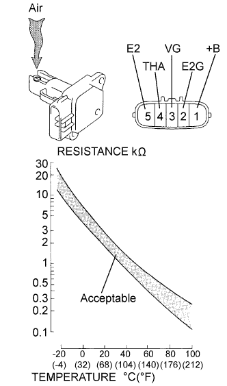

Turn the ignition switch and tester ON.
Enter the following menus: Powertrain / Engine / Data List / MAF.
- Standard:
- 0.54 g/s or less
Inspect resistance.
Measure the resistance between the terminals of the mass air flow meter.
- Standard resistance:
Tester Connection
Specified Condition
THA (4) - E2 (5)
13.6 to 18.4 kΩ at -20°C (-4°F)
THA (4) - E2 (5)
2.21 to 2.69 kΩ at 20°C (68°F)
THA (4) - E2 (5)
0.49 to 0.67 kΩ at 60°C (140°F)
Reinstall the mass air flow meter.
|
|
||||
| OK | |
|
| 7. INSPECT ENGINE COOLANT TEMPERATURE SENSOR |
Remove the engine coolant temperature sensor.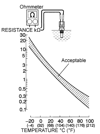
Measure the resistance between the terminals of the engine coolant temperature sensor.
- Standard resistance:
Tester Connection
Specified Condition
1 - 2
2 to 3 kΩ at 20°C (68°F)
1 - 2
0.2 to 0.4kΩ at 80°C (176°F)
- NOTICE:
- In case of checking the engine coolant temperature sensor in water, be careful not to allow water to contact the terminals. After checking, dry the sensor.
- HINT:
- Alternate procedure: Connect an ohmmeter to the installed engine coolant temperature sensor and read the resistance. Use an infrared thermometer to measure the engine temperature in the immediate vicinity of the sensor. Compare these values to the resistance/temperature graph. Change the engine temperature (warm up or allow to cool down) and repeat the test.
Reinstall the engine coolant temperature sensor.
|
|
||||
| OK | |
|
| 8. INSPECT CRANKSHAFT POSITION SENSOR |
Disconnect the C3 crankshaft position sensor connector.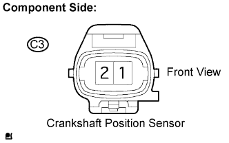
Measure the resistance between the terminals of the crankshaft position sensor connector.
- Standard resistance:
Tester Connection
Specified Condition
1 - 2
985 to 1,600 Ω at cold
1 - 2
1,265 to 1,890 Ω at hot
Reconnect the crankshaft position sensor connector.
- NOTICE:
- Terms "cold" and "hot" refer to the temperature of the coils. "Cold" means approximately -10°C to 50°C (14°F to 122°F). "Hot" means approximately 50°C to 100°C (122°F to 212°F).
|
|
||||
| OK | |
|
| 9. INSPECT CAMSHAFT POSITION SENSOR |
Disconnect the V6 and V5 camshaft position sensor connector.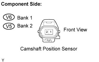
Measure the resistance between the terminals of camshaft position sensor connector.
- Standard resistance:
Tester Connection
Specified Condition
1 - 2
1,630 to 2,740 Ω at cold
1 - 2
2,065 to 3, 225 Ω at hot
Reconnect the camshaft position sensor connector.
- NOTICE:
- Terms "cold" and "hot" refer to the temperature of the coils. "Cold" means approximately -10°C to 50°C (14°F to 122°F). "Hot" means approximately 50°C to 100°C (122°F to 212°F).
|
|
||||
| OK | |
|
| 10. INSPECT THROTTLE CONTROL MOTOR |
Disconnect the throttle control motor connector.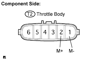
Using an ohmmeter, measure the motor resistance between terminals 1 (M-) and 2 (M+).
- Standard resistance:
Tester Connection
Specified Condition
1 - 2
0.3 to 100 Ω at 20°C (68°F)
|
|
||||
| OK | |
|
| 11. INSPECT THROTTLE POSITION SENSOR |
Connect the intelligent tester to the DLC3.
Turn the ignition switch ON and turn the intelligent tester ON.
Enter the following menus: Powertrain / Engine / Data List / Throttle Sens Open Pos #1 and Throttle Sens Open Pos #2.
Check the values displayed on the tester.
- Standard voltage:
Item
Condition
Specified Condition
Throttle Sens Open Pos #1
Throttle fully closed
2.15 to 2.35 V
Throttle fully open
4.5 to 5.0 V
Throttle Sens Open Pos #2
Throttle fully closed
0.66 to 0.76 V
Throttle fully open
3.8 to 4.2 V
|
|
||||
| OK | ||
 |
||
| ||