Entire Combination Meter does not Operate
Circuit diagnosis
WIRING DIAGRAM
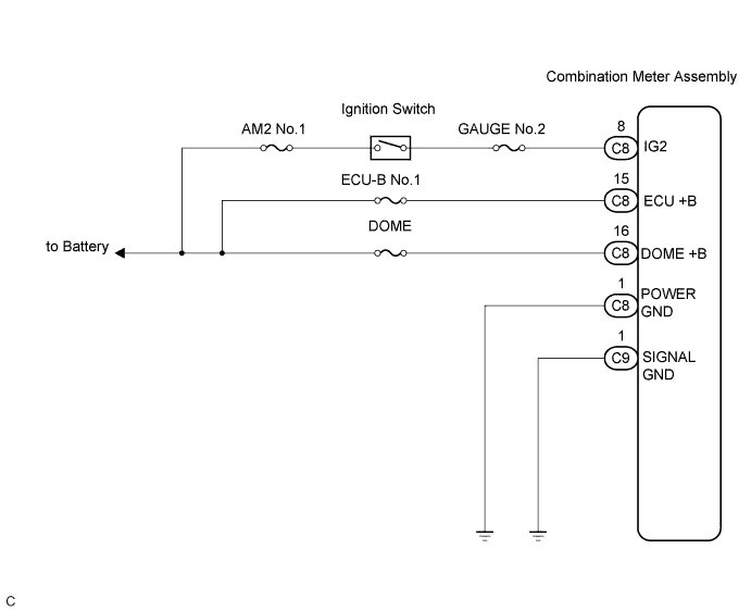

INSPECTION PROCEDURE
| 1. INSPECT COMBINATION METER ASSEMBLY |

Disconnect the C8 and C9 connectors.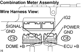
Measure the resistance according to the value(s) in the table below.
- Standard Resistance:
Tester Connection
Condition
Specified Condition
C8-1 (POWER GND)
- Body ground
Always
Below 1 Ω
C9-1 (SIGNAL GND)
- Body ground
Always
Below 1 Ω
Measure the voltage according to the value(s) in the table below.
- Standard Voltage:
Tester Connection
Condition
Specified Condition
C8-8 (IG2) -
Body ground
Turn the ignition switch to the ON position
10 to 16 V
C8-15 (ECU +B) -
Body ground
Always
10 to 16 V
C8-16 (DOME +B) -
Body ground
Always
10 to 16 V
|
|
||||

| OK | ||
 |
||
| ||