INSTALLATION
Removal / installation
| 1. INSTALL OIL PUMP SEAL |

Using SST and a hammer, tap in a new oil seal until its surface is flush with the oil pump body edge.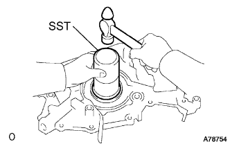

- SST
- 09223-00010
- NOTICE:
- Do not tap the oil seal at an angle.
- Keep the lip free from foreign objects.
- Do not tap the oil seal at an angle.
Apply MP grease to the oil seal lip.
| 2. INSTALL OIL PUMP ASSEMBLY |
Remove any old seal packing material from the contact surface.
Apply a light coat of engine oil to a new O-ring and place it on the cylinder block.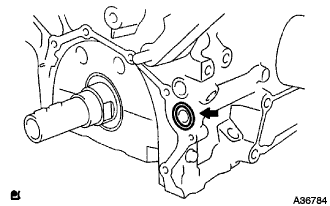
Apply a continuous bead of seal packing (Diameter 2 to 3 mm (0.08 to 0.12 in.)) as shown in the illustration.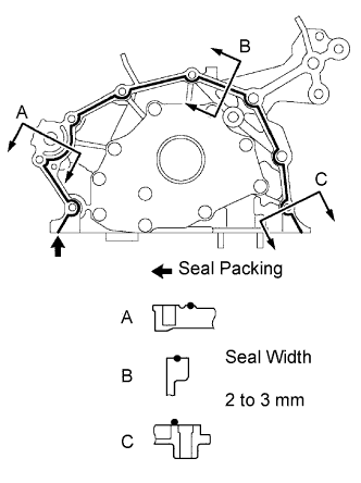
- Seal packing:
- Part No. 08826-00080 or equivalent
- NOTICE:
- Remove any oil from the contact surface.
- Apply seal packing to the inner side of the bolt holes.
- Install the oil pump within 3 minutes after applying seal packing.
- Do not expose the seal to engine oil within 2 hours after installing.
- Remove any oil from the contact surface.
Align the key of the oil pump drive gear with the keyway located on the crankshaft, and slide the oil pump into place.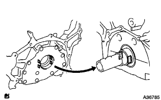
Install the oil pump with the 9 bolts. Tighten the bolts uniformly in several steps.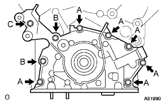
- Torque:
- Bolt A:
- 8.0 N*m{ 82 kgf*cm , 71 in.*lbf }
- Bolt B:
- 20 N*m{ 199 kgf*cm , 14 ft.*lbf }
- Bolt C:
- 43 N*m{ 439 kgf*cm , 32 ft.*lbf }
| 3. INSTALL CRANK POSITION SENSOR |
- Torque:
- 8.0 N*m{ 80 kgf*cm , 71 in.*lbf }
| 4. INSTALL OIL PAN SUB-ASSEMBLY |
Remove any old seal packing from the contact surface.
Apply a continuous bead of seal packing (Diameter 3 to 4 mm (0.12 to 0.16 in.)) as shown in the illustration.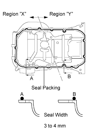
- Seal packing:
- Part No. 08826-00080 or equivalent
- NOTICE:
- Remove any oil from the contact surface.
- Apply seal packing to the outer side of the bolt holes in the region "X".
- Apply seal packing to the inner side of the bolt holes in the region "Y".
- Install the oil pan within 3 minutes after applying seal packing.
- Do not expose the seal to engine oil within 2 hours after installing.
- Remove any oil from the contact surface.
Install oil pan sub-assembly with the 17 bolts. Tighten the bolts uniformly in several steps.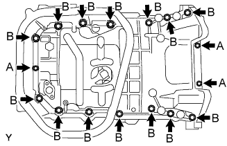
- Torque:
- 10 mm Bolt A:
- 8.0 N*m{ 82 kgf*cm , 71 in.*lbf }
- 12 mm Bolt B:
- 20 N*m{ 199 kgf*cm , 14 ft.*lbf }
| 5. INSTALL OIL STRAINER SUB-ASSEMBLY |
Install a new gasket and the oil strainer with the bolt and 2 nuts.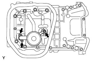
- Torque:
- 8.0 N*m{ 82 kgf*cm , 71 in.*lbf }
| 6. INSTALL OIL PAN SUB-ASSEMBLY NO.2 |
Remove any old seal packing from the contact surface.
Apply a continuous bead of seal packing (Diameter 4 to 5 mm (0.16 to 0.20 in.)) as shown in the illustration.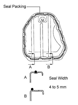
- Seal packing:
- Part No. 08826-00080 or equivalent
- NOTICE:
- Remove any oil from the contact surface.
- Apply seal packing to the inner side of the bolt holes.
- Install the oil pan within 3 minutes after applying seal packing.
- Do not expose the seal to engine oil within 2 hours after installing.
- Remove any oil from the contact surface.
Install oil pan No.2 with the 10 bolts and 2 nuts.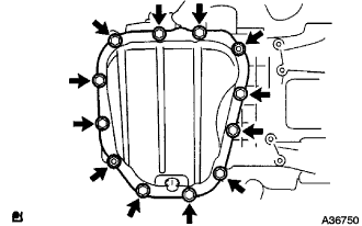
- Torque:
- 8.0 N*m{ 82 kgf*cm , 71 in.*lbf }
| 7. INSTALL CRANKSHAFT TIMING PULLEY |
Align the keyway of the pulley with the key located on the crankshaft and slide the pulley into place.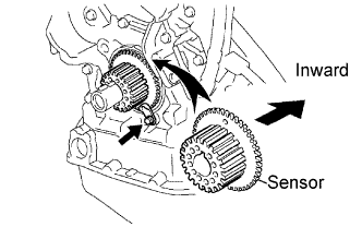
- NOTICE:
- Do not scratch the sensor area of the crankshaft timing pulley.
Install the timing belt plate with the bolt.
- Torque:
- 8.0 N*m{ 82 kgf*cm , 71 in.*lbf }
| 8. INSTALL TIMING BELT IDLER SUB-ASSEMBLY NO.1 |
Using a socket hexagon wrench 10 mm, install the plate washer and timing belt idler No.1 with the pivot bolt.
- Torque:
- 34 N*m{ 347 kgf*cm , 25 ft.*lbf }
| 9. INSTALL TIMING BELT |
Remove any oil or water on the pulleys, and keep them clean.
- NOTICE:
- If there is a trace of water and/or oil on the timing belt, repair the leakage and install a new timing belt.
- Wipe only the pulleys; do not use any cleaning agent.
- If there is a trace of water and/or oil on the timing belt, repair the leakage and install a new timing belt.
Inspect the idler pulleys.
Check that the idler pulley turns smoothly.
Visually check the seal portion of the idler pulley for oil leakage.
Inspect the water pump.
Turn the pulley, and check that the water pump bearing moves smoothly and does not make any noise.
Visually check the drain hole for coolant leakage.
Temporarily install the crankshaft pulley bolt and washer to the crankshaft.
Turn the crankshaft counterclockwise by approximately 60°.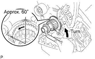
- NOTICE:
- To prevent contacting the piston head and the valve head, set the crankshaft pulley at 60° BTDC/compression position.
Using SST, turn the timing pulleys, and align the timing marks of the timing pulleys with the No.3 timing belt cover.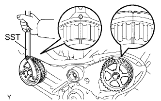
- SST
- 09960-10010
(09962-01000, 09963-01000)
- NOTICE:
- Be sure to hold the SST with the timing marks aligned to prevent the left bank pulley from deviating to the right.
Turn the crankshaft, and align the timing mark of the crankshaft timing pulley with the oil pump body.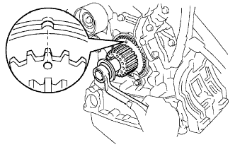
Face the front mark on the timing belt forward.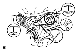
Align the installation mark on the timing belt with the timing mark of the crankshaft timing pulley.
Align the installation marks on the timing belt with the timing marks of the camshaft timing pulleys.
Install the timing belt in the following order.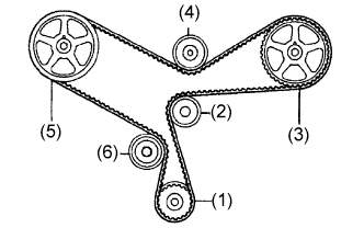
1st
Crankshaft timing pulley
2nd
Water pump pulley
3rd
LH camshaft timing pulley
4th
No.2 idler pulley
5th
RH camshaft timing pulley
6th
No.1 idler pulley
- NOTICE:
- Be sure to hold the SST with the timing marks aligned to prevent the left bank pulley from deviating to the right.
| 10. INSTALL CHAIN TENSIONER ASSEMBLY NO.1 |
Set the timing belt tensioner upright on the press.
Slowly press in the push rod.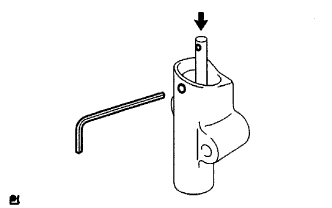
- NOTICE:
- Do not apply pressure more than 9.8 kN (1,000 kgf, 2,205 lbf) to the rod.
Align the holes of the push rod and housing, and pass a 1.5 mm hexagon wrench through the holes to keep the setting position of the push rod.
Release the press.
Temporarily install the tensioner with the 2 bolts. Alternately tighten the 2 bolts.
- Torque:
- 27 N*m{ 280 kgf*cm , 20 ft.*lbf }
- NOTICE:
- Be sure to tighten the bolts equally. Installing the tensioner at an angle may cause improper operation.
Remove the 1.5 mm hexagon wrench from the tensioner.
Turn the crankshaft 2 revolutions slowly and align the timing mark of the crankshaft timing pulley with the oil pump body.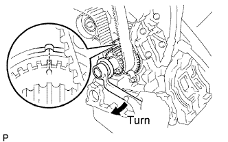
- NOTICE:
- Always turn the crankshaft clockwise.
Check the timing marks of the RH and LH timing pulleys are aligned with the timing marks of the No.3 timing belt cover as shown in the illustration.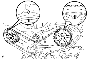
If the marks do not align, remove the timing belt and reinstall it.
Remove the crankshaft pulley bolt.
| 11. INSTALL TIMING BELT GUIDE NO.2 |
Install the timing belt guide with the cup side facing toward the engine front.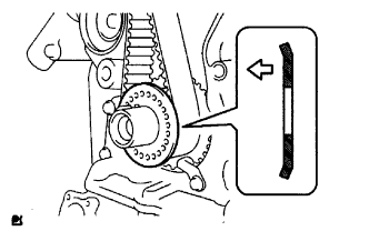
| 12. INSTALL ENGINE MOUNTING BRACKET RH |
Install the engine mounting bracket RH with the 2 bolts and 2 nuts.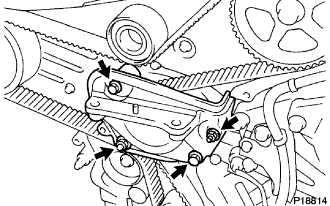
- Torque:
- 28 N*m{ 286 kgf*cm , 21 ft.*lbf }
| 13. INSTALL TIMING BELT NO.2 COVER |
Visually check for cracks and breaks on the gasket of the timing belt cover.
If a trace of water is found in the visual check, replace the timing belt cover.
Install the timing belt cover with the 5 bolts.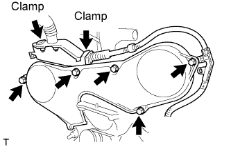
- Torque:
- 8.5 N*m{ 87 kgf*cm , 75 in.*lbf }
Connect the 2 clamps.
| 14. INSTALL TIMING BELT NO.1 COVER |
Visually check for cracks and breaks on the gasket of the timing belt cover.
If a trace of water is found in the visual check, replace the timing belt cover.
Install the timing belt cover.
- Torque:
- 8.5 N*m{ 87 kgf*cm , 75 in.*lbf }
Install the engine wire protector cover to the timing belt No.3 cover.
| 15. INSTALL OIL LEVEL GAGE SUB-ASSEMBLY |
Install the oil level gage sub-assembly.
| 16. INSTALL COMPRESSOR MOUNTING BRACKET NO.1 |
Temporarily install the mounting bracket with the 4 bolts.
Install the mounting bracket by tightening the 4 bolts in the order shown in the illustration.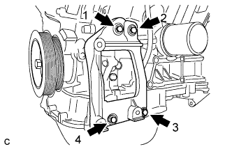
| 17. INSTALL ENGINE MOUNTING STAY BRACKET |
Install the 3 bolts, nut and engine mounting stay bracket.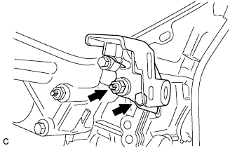
- Torque:
- 52 N*m{ 530 kgf*cm , 38 ft.*lbf }
| 18. INSTALL ENGINE MOUNTING BRACKET RH |
Install the 3 bolts and engine mounting bracket RH.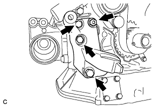
- Torque:
- 54 N*m{ 551 kgf*cm , 40 ft.*lbf }
| 19. INSTALL CRANKSHAFT PULLEY |
Align the keyway of the pulley with the key located on the crankshaft and slide the pulley into place.
Using SST, install the pulley bolt.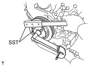
- SST
- 09213-54015
(91651-60855)
09330-00021
- Torque:
- 220 N*m{ 2,243 kgf*cm , 162 ft.*lbf }
| 20. INSTALL MANIFOLD STAY NO.2 |
Install the 2 bolts and manifold stay No.2.
- Torque:
- 49 N*m{ 500 kgf*cm , 36 ft.*lbf }
| 21. INSTALL EXHAUST MANIFOLD CONVERTER SUB-ASSEMBLY NO.2 |
Install a new gasket as shown in the illustration.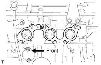
Install the exhaust manifold converter No.2 with the 6 nuts and bolt. Using several steps, tighten the nuts uniformly in the sequence shown in the illustration.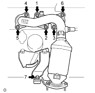
- Torque:
- 49 N*m{ 500 kgf*cm , 36 ft.*lbf }
Retighten nuts 1 and 2 shown in the illustration.
| 22. INSTALL EXHAUST MANIFOLD HEAT INSULATOR NO.2 |
Install the 2 bolts and exhaust manifold heat insulator No.2.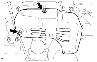
- Torque:
- 8.5 N*m{ 87 kgf*cm , 75 in.*lbf }
| 23. INSTALL MANIFOLD CONVERTER INSULATOR NO.3 |
Install the bolt, nut and manifold converter insulator No.3.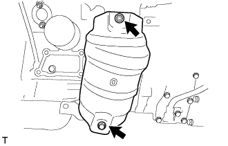
- Torque:
- 8.5 N*m{ 87 kgf*cm , 75 in.*lbf }
| 24. REMOVE ENGINE STAND |
| 25. INSTALL FLYWHEEL SUB-ASSEMBLY |
Using SST, hold the crankshaft.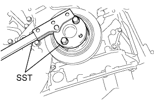
- SST
- 09213-54015
(91651-60855)
09330-00021
Clean the bolts and bolt holes.
Apply adhesive to 2 or 3 threads of the bolts.
- Adhesive:
- Part No.08833-00070, THREE BOND 1324 or equivalent
Install the flywheel on the crankshaft.
Using several steps, install and tighten the 8 bolts uniformly in the sequence shown in the illustration.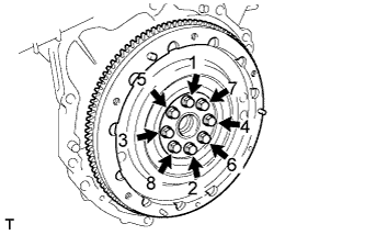
- Torque:
- 83 N*m{ 846 kgf*cm , 61 ft.*lbf }
- NOTICE:
- Do not start the engine within 1 hour after installing.
| 26. INSTALL TRANSMISSION INPUT DAMPER ASSEMBLY |
Using SST, hold the crankshaft.
- SST
- 09213-54015
(91651-60855)
09330-00021
Install the 6 bolts and transmission input damper.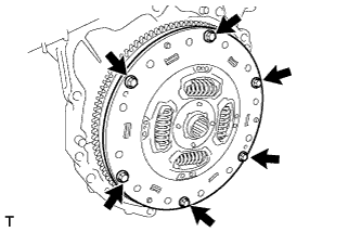
- Torque:
- 30 N*m{ 306 kgf*cm , 22 ft.*lbf }
- HINT:
- Take care not to insert the transmission input damper in the wrong direction.
| 27. INSTALL HYBRID VEHICLE TRANSAXLE ASSEMBLY |
Make sure that the knock pins are installed on the engine.
Install the hybrid vehicle transaxle and the 8 bolts shown in the illustration to the engine.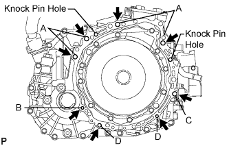
- Torque:
- Bolt A:
- 64 N*m{ 653 kgf*cm , 47 ft.*lbf }
- Torque:
- Bolt B:
- 46 N*m{ 469 kgf*cm , 34 ft.*lbf }
- Torque:
- Bolt C:
- 64 N*m{ 653 kgf*cm , 47 ft.*lbf }
- Torque:
- Bolt D:
- 37 N*m{ 377 kgf*cm , 27 ft.*lbf }
- NOTICE:
- Do not reuse bolt B.
- Do not forcibly pry out the hybrid vehicle transaxle assembly
- Do not apply the grease either to the spline or to the input shaft.
- Do not reuse bolt B.
Bolt
Installation direction
Diameter
Bolt length
A
From transaxle to engine
12 mm (0.47 in.)
55 mm (2.17 in.)
B
From engine to transaxle
10 mm (0.39 in.)
55 mm (2.17 in.)
C
From transaxle to engine
12 mm (0.47 in.)
55 mm (2.17 in.)
D
From engine to transaxle
10 mm (0.39 in.)
33 mm (1.30 in.)
| 28. INSTALL ENGINE MOUNTING BRACKET FRONT |
Install the engine mounting bracket front with the 3 bolts.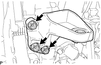
- Torque:
- 64 N*m{ 653 kgf*cm , 47 ft.*lbf }
| 29. INSTALL FLYWHEEL HOUSING UNDER COVER |
Install the flywheel housing under cover with the 2 bolts.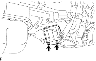
- Torque:
- 7.8 N*m{ 80 kgf*cm , 69 in.*lbf }
| 30. INSTALL FRONT DRIVE SHAFT ASSEMBLY LH |
Install a new drive shaft hole snap ring.
Coat the spline of the inboard joint shaft assembly with ATF.
Align the shaft splines and install the drive shaft assembly with a brass bar and a hammer.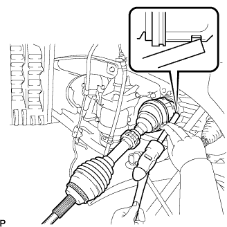
- NOTICE:
- Set the snap ring with the opening side facing down.
- Be careful not to damage the drive shaft dust cover, boot, or oil seal.
- Set the snap ring with the opening side facing down.
| 31. INSTALL FRONT DRIVE SHAFT ASSEMBLY RH |
Coat the spline of the inboard joint shaft assembly with ATF.
Align the shaft splines and install the drive shaft assembly.
- NOTICE:
- Be careful not to damage the drive shaft dust cover, boot, or oil seal.
Using pliers, install a new bearing bracket hole snap ring.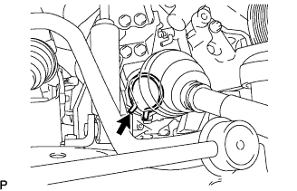
Install a new bolt to the drive shaft bearing bracket.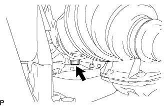
- Torque:
- 32 N*m{ 330 kgf*cm , 24 ft.*lbf }
| 32. INSTALL FRONT FRAME ASSEMBLY |
Install the engine mounting insulators RH and LH with the 2 nuts.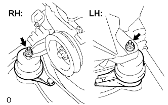
- Torque:
- 95 N*m{ 969 kgf*cm , 70 ft.*lbf }
Install the engine mounting insulator FR with the nut.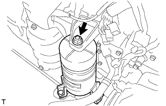
- Torque:
- 87 N*m{ 887 kgf*cm , 64 ft.*lbf }
Install the engine mounting insulator RR with the 2 bolts.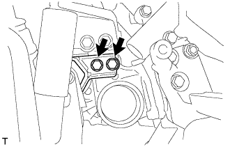
- Torque:
- 75 N*m{ 765 kgf*cm , 55 ft.*lbf }
| 33. INSTALL HV TRANSAXLE MASS DAMPER |
Install the bolt and transaxle mass damper.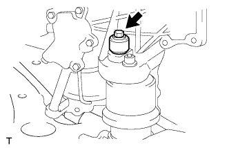
- Torque:
- 14 N*m{ 138 kgf*cm , 10 ft.*lbf }
| 34. INSTALL EXHAUST MANIFOLD SUB-ASSEMBLY RH |
Install a new gasket as shown in the illustration.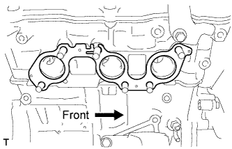
Install a new gasket and the exhaust manifold RH with the 6 nuts. Using several steps, tighten the nuts uniformly in the sequence shown in the illustration.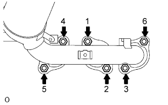
- Torque:
- 49 N*m{ 500 kgf*cm , 36 ft.*lbf }
Retighten nuts 1 and 2 shown in the illustration.
| 35. INSTALL MANIFOLD STAY |
Temporarily install the manifold stay to the exhaust manifold and transaxle.
Fully tighten the 2 bolts.
- Torque:
- 34 N*m{ 347 kgf*cm , 25 ft.*lbf }
| 36. INSTALL EXHAUST MANIFOLD HEAT INSULATOR NO.1 |
Install the 3 bolts and exhaust manifold heat insulator No.1.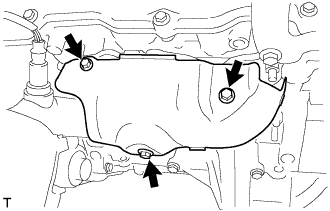
- Torque:
- 8.5 N*m{ 87 kgf*cm , 75 in.*lbf }
| 37. INSTALL ENGINE WIRE |
| 38. INSTALL ENGINE ASSEMBLY WITH TRANSAXLE |