01-DD
Diagnostic trouble codes
DESCRIPTION
| DTC No. |
DTC Detection Condition |
Trouble Area |
| 01-DD *1 |
The device that should be the master has been disconnected after engine start |
|
| 01-E1 *2 |
The AMP device records that the AMP output does not function even while the source device operates |
- HINT:
- *1: This code may be stored if the engine is started and the ignition switch is turned to the START position again.
- *2: Even if no failure is detected, a trouble code may be recorded depending on the battery condition or engine start voltage.
- *1: This code may be stored if the engine is started and the ignition switch is turned to the START position again.
- NOTICE:
- Be sure to clear and recheck DTCs and perform inspection according to the result to avoid the conditions shown in "HINT" above.
- The multi-display is the master unit.
- Be sure to clear and recheck DTCs after the inspection is completed to confirm that no DTCs are output.
- Be sure to clear and recheck DTCs and perform inspection according to the result to avoid the conditions shown in "HINT" above.
INSPECTION PROCEDURE
- NOTICE:
- Be sure to read DESCRIPTION before performing the following procedures.
| 1. CHECK MULTI-DISPLAY POWER SOURCE CIRCUIT |

If the power source circuit is operating normally, proceed to the next step.
| NEXT | |
 |
| 2. INSPECT RADIO RECEIVER |
Disconnect the radio receiver connectors.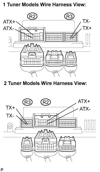

Measure the resistance according to the value(s) in the table below.
- Resistance:
Tester Connection
Condition
Specified Condition
ATX+ (R2-5) -
ATX- (R2-15)
Always
60 to 80 Ω
TX+ (R3-9) -
TX- (R3-10)
Always
60 to 80 Ω
|
|
||||

| OK | |
|
| 3. IDENTIFY THE COMPONENT WHICH HAS STORED THIS CODE |
Enter the diagnostic mode.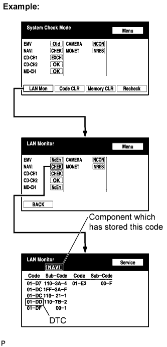
Press the "LAN Mon" switch to change to "LAN Monitor" mode.
Identify the component which has stored this code.
Component Table Display
Component
AUDIO H/U
Radio Receiver
DSP-AMP
Stereo Component Amplifier
G/W
Gateway ECU
NAVI
Navigation ECU
CAMERA
Television Camera ECU
- HINT:
- "NAVI" is the component which has stored this code in the example shown in the illustration.
| NEXT | |
|
| 4. CHECK HARNESS AND CONNECTOR (MULTI-DISPLAY - COMPONENT WHICH HAS STORED THIS CODE) |
- HINT:
- For details of the connectors, refer to the "Terminals of ECU" (Click here).
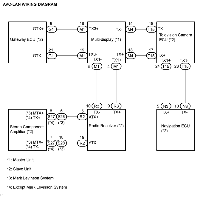
Referring to the AVC-LAN wiring diagram below, check the AVC-LAN circuit between the multi-display and the component which has stored this code.
Check for an open or short in the AVC-LAN circuit between the multi-display and the component which has stored this code.
- OK:
- There is no open or short circuit.
|
|
||||
| OK | |
|
| 5. REPLACE MULTI-DISPLAY |
Replace the multi-display with a normal one and check if the same problem occurs again.
- OK:
- Same problem does not occur.
|
|
||||
| OK | ||
 |
||
| ||