P0AD2 Voltage at each battery assembly (V0, V1 and V2) is out of the predetermined range in proportion to the...
Diagnostic trouble codes
DESCRIPTION
Refer to description to DTC P0A84. (Click here)| DTC No. |
DTC Detection Condition |
Trouble Area |
| P0AD2 P0AD3 |
Voltage at each battery assembly (V0, V1 and V2) is out of the predetermined range in proportion to the target control voltage (1 trip detection). |
|
WIRING DIAGRAM
Refer to wiring diagram to DTC P0A84. (Click here)INSPECTION PROCEDURE
| 1. READ OUTPUT DTC |

Connect the intelligent tester to the DLC3.
Turn the ignition switch to the ON position.
Select the following menu items: Powertrain / Hybrid Control / DTC.
Read output DTCs. (Click here)
- Result:
DTC output
Proceed to
Either or both of P0AD2 and P0AD3 is/are output
A
3 or more of P0A84, P0A85, P0A99, P0A9A, P0AD2 and P0AD3 are output
B
|
|
||||

| A | |
 |
| 2. CHECK BATTERY COOLING BLOWER ASSEMBLY |
- CAUTION:
- Be sure to wear insulated gloves and protective goggles.
Connect the intelligent tester to the DLC3.
Select the following menu items: Powertrain / Hybrid Control / Data List / VMF Fan Voltage 1 to 3 and Batt Temp 1 to 8.
- HINT:
- Easier to see the change in the VMF Fan Voltage when displayed in the line chart.
Perform a driving test and check that there is a malfunction in the VMF Fan Voltage 3 while the battery cooling blower No.2 is operating. (*1)
- HINT:
- The fan operates when the battery temperature is approximately 36°C (97°F) or more.
- VMF Fan Voltage 3 in the Data List represents the battery cooling blower assembly No.2 voltage.
- The fan operates when the battery temperature is approximately 36°C (97°F) or more.
Remove the battery cover and replace the battery cooling blower assembly No.2 with the battery cooling blower assembly No.0 or No.1. (Click here)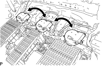

Install the battery cover. (Click here)
Select the following menu items: Powertrain / Hybrid Control / Data List / VMF Fan Voltage 1 to 3 and Batt Temp 1 to 8.
- HINT:
- Easier to see the change in the VMF Fan Voltage when displayed in the line chart.
Perform a driving test and check that a malfunction in (*1) is reproduced in the battery cooling blower No.0 or No.1.
- Standard:
- The malfunction is reproduced in another battery cooling blower.
- HINT:
- The battery cooling blower operates when the battery temperature is approximately 36°C (97°F) or more.
|
|
||||

| NO | |
|
| 3. CHECK HARNESS AND CONNECTOR (BATT FAN RELAY - BATTERY COOLING BLOWER ASSEMBLY) |
- CAUTION:
- Be sure to wear insulated gloves and protective goggles.
Remove the battery cover. (Click here)
Disconnect the 2D connector from the engine room J/B No.2.
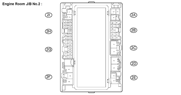
Disconnect the B23 battery blower assembly (No.2) connector.
Measure the resistance according to the value(s) in the table below.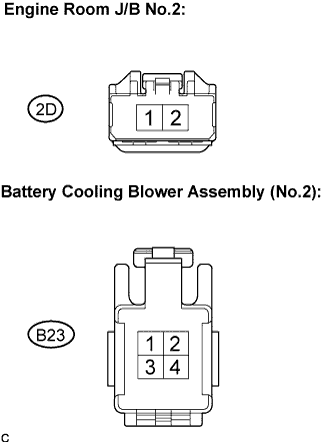
- Standard Resistance:
Tester Connection
Specified Condition
Engine room J/B No.2 (2D-1) - Battery cooling blower assembly (No.2) (B23-1)
Below 1 Ω
|
|
||||
| OK | |
|
| 4. CHECK HARNESS AND CONNECTOR (BATTERY COOLING BLOWER ASSEMBLY - BATTERY SMART UNIT) |
- CAUTION:
- Be sure to wear insulated gloves and protective goggles.
Disconnect the B26 connector from the battery smart unit.
Measure the resistance according to the value(s) in the table below.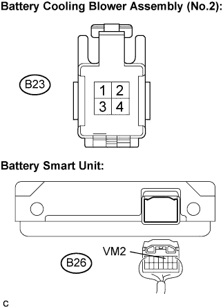
- Standard Resistance (Check for open):
Tester Connection
Specified Condition
Battery cooling blower assembly (No.2) (B23-2) - VM2 (B26-5)
Below 1 Ω
- Standard Resistance (Check for short):
Tester Connection
Specified Condition
Battery cooling blower assembly (No.2) (B23-2) - Body ground
10 kΩ or more
|
|
||||
| OK | |
|
| 5. CHECK HARNESS AND CONNECTOR (BATTERY COOLING BLOWER ASSEMBLY - BODY GROUND) |
- CAUTION:
- Be sure to wear insulated gloves and protective goggles.
Measure the resistance according to the value(s) in the table below.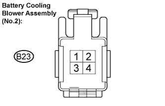
- Standard Resistance:
Tester Connection
Specified Condition
Battery cooling blower assembly (No.2) (B23-4) - Body ground
10 kΩ or more
|
|
||||
| OK | |
|
| 6. CHECK HARNESS AND CONNECTOR (BATTERY COOLING BLOWER ASSEMBLY (NO.3) - HV CONTROL ECU) |
- CAUTION:
- Be sure to wear insulated gloves and protective goggles.
Disconnect the H30 connector from the HV control ECU.
Measure the resistance according to the value(s) in the table below.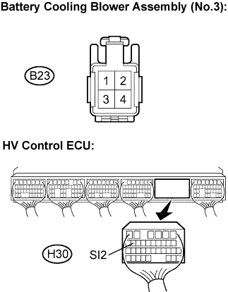
- Standard Resistance (Check for open):
Tester Connection
Specified Condition
Battery cooling blower assembly (No.2) (B23-3) - SI2 (H30-13)
Below 1 Ω
- Standard Resistance (Check for short):
Tester Connection
Specified Condition
Battery cooling blower assembly (No.2) (B23-3) - Body ground
10 kΩ or more
|
|
||||
| NG | ||
 |
||
| ||
| 7. CHECK FUSE (BATT FAN) |
Remove the BATT FAN fuse from the engine room R/B No.4.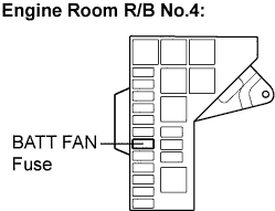
Check the continuity of the BATT FAN fuse.
- Standard Resistance:
- Below 1 Ω
|
|
||||
| OK | |
|
| 8. CHECK MODE MONITOR TERMINAL (BATT FAN RELAY) |
Preparation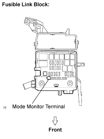
Connect the connector.
Remove the cover of the fusible link block assembly.
Set the vehicle to the following condition.
- Ignition switch ON.
- Headlight dimmer switch LO.
- Ignition switch ON.
Check voltage
Measure the voltage between the Mode Monitor Terminal and body ground.
- Standard Voltage:
Result
Proceed to
0 V or Approx. 12 V
A
Approx. 6.2 V
B
Approx. 2.0 V
C
|
|
||||
|
|
||||
| A | |
|
| 9. CHECK HARNESS AND CONNECTOR (ENGINE ROOM J/B NO.2 - MODE MONITOR TERMINAL) |
Disconnect the 2G connector from the engine room J/B No.2.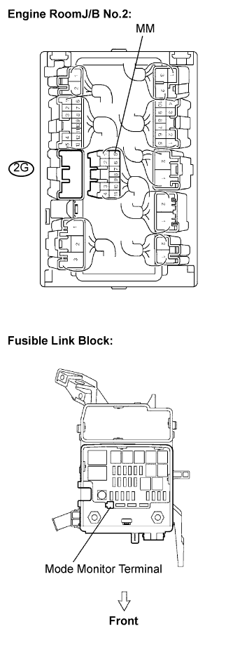
Measure the resistance according to the value(s) in the table below.
- Standard Resistance:
Tester Connection
Condition
Specified Condition
2G-5 - Mode monitor terminal
Always
Below 1 Ω
2G-5 - Body ground
Always
10 kΩ or higher
|
|
||||
| OK | |
|
| 10. INSPECT ENGINE ROOM J/B NO.2 (BATT FAN RELAY) |
Turn the ignition switch off.
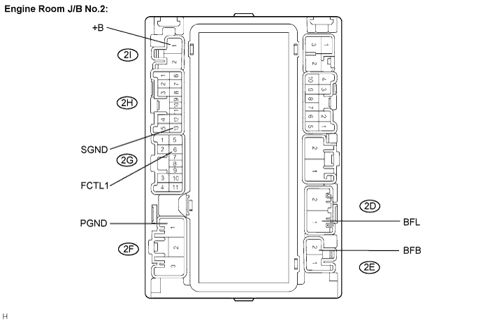
Remove the engine room J/B No.2.
Connect the positive battery lead to terminal BFB of the engine room J/B No.2 and the negative lead to terminal SGND, PGND.
Symbols (terminals No.)
Connection
BFB (2E-2) - SGND (2N-13) and PGND (2F-1)
Positive - Negative
Measure the voltage according to the value(s) in the table below.
- Standard Voltage:
Tester Connection
Specified Condition
BFL (2D-1) - Battery negative terminal
Below 1 V
Connect the battery negative lead to terminal FCTL1 of the engine J/B No.2.
Symbols (terminals No.)
Connection
FCTL1 (2G-6)
Negative
Measure the voltage according to the value(s) in the table below.
- Standard Voltage:
Tester Connection
Specified Condition
BFL (2D-1) - Battery negative terminal
10 to 14 V
|
|
||||
| OK | |
|
| 11. CHECK HARNESS AND CONNECTOR (BATT FAN RELAY - BATT FAN FUSE) |
Disconnect the 2E connector from the engine room J/B No.2.
Remove the BATT FAN fuse from the engine room R/B No.4.
Measure the resistance according to the value(s) in the table below.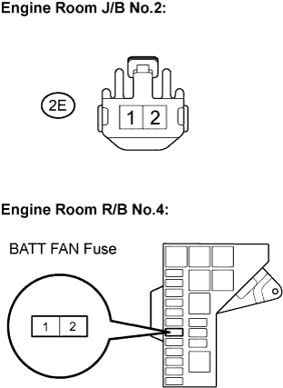
- Standard Resistance:
Tester Connection
Specified Condition
Engine Room J/B No.2 (2E-2) - Engine Room R/B No.4 BATT FAN fuse terminal 2.
Below 1 Ω
- NOTICE:
- When taking a measurement with a tester, do not apply excessive force to the tester probe to avoid damaging the holder.
|
|
||||
| OK | |
|
| 12. CHECK HARNESS AND CONNECTOR (BATT FAN RELAY - BATTERY COOLING BLOWER ASSEMBLY) |
- CAUTION:
- Be sure to wear insulated gloves and protective goggles.
Remove the battery cover.
Disconnect the 2D connector from the engine room J/B No.2.
Disconnect each of the 3 battery cooling blower assembly (No.0, No.1 and No.2) connectors.
Measure the resistance according to the value(s) in the table below.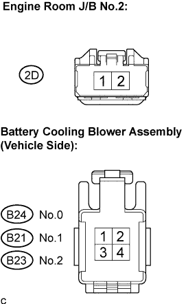
- Standard Resistance:
Tester Connection
Specified Condition
Engine Room J/B No.2 (2D-1) - Battery cooling blower (1)
Below 1 Ω
|
|
||||
| OK | |
|
| 13. CHECK HARNESS AND CONNECTOR (BATT FAN RELAY - HV CONTROL ECU) |
Disconnect the 2G connector from the engine room J/B No.2.
Disconnect the H31 connector from the HV control ECU.
Measure the resistance according to the value(s) in the table below.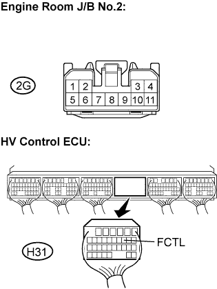
- Standard Resistance (Check for open):
Tester Connection
Specified Condition
Engine Room J/B No.2 (2G-6) - FCTL (H31-6)
Below 1 Ω
- Standard Resistance (Check for short):
Tester Connection
Specified Condition
Engine Room J/B No.2 (2G-6) - Body ground
10 kΩ or higher
|
|
||||
| NG | ||
|
||
| ||
| 14. CHECK HARNESS AND CONNECTOR (BATT FAN RELAY - BATT FAN FUSE) |
Disconnect the 2E connector from the engine room J/B No.2.
Remove the BATT FAN fuse from the engine room R/B No.4.
Measure the resistance according to the value(s) in the table below.
- Standard Resistance:
Tester Connection
Specified Condition
Engine Room J/B No.2 (2E-2) - Body ground
10 kΩ or higher
- NOTICE:
- When taking a measurement with a tester, do not apply excessive force to the tester probe to avoid damaging the holder.
|
|
||||
| OK | |
|
| 15. CHECK HARNESS AND CONNECTOR (BATT FAN RELAY - BATTERY COOLING BLOWER ASSEMBLY) |
- CAUTION:
- Be sure to wear insulated gloves and protective goggles.
Remove the battery cover. (Click here)
Disconnect the 2D connector from the engine room J/B No.2.
Disconnect each of the 3 battery blower assembly (No.1, No.2 and No.3) connectors.
Measure the resistance according to the value(s) in the table below.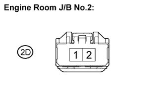
- Standard Resistance:
Tester Connection
Specified Condition
Engine Room J/B No.2 (2D-1) - Body ground
10 kΩ or higher
|
|
||||
| OK | |
|
| 16. INSPECT BATTERY COOLING BLOWER ASSEMBLY |
- CAUTION:
- Be sure to wear insulated gloves and protective goggles.
Measure the resistance according to the value(s) in the table below.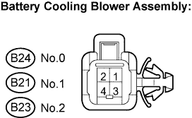
- Standard Resistance:
Tester Connection
Specified Condition
Battery cooling blower assembly (1) - Body ground
10 kΩ or higher
|
|
||||
| OK | ||
|
||
| ||
| 17. INSPECT HYBRID VEHICLE CONTROL ECU |
- HINT:
- By using the oscilloscope function in the intelligent tester, inspection of the function between the HV control ECU and battery smart unit can be conducted.
Install the battery cover. (Click here)
Using an oscilloscope, measure the waveform according to the condition in the table below.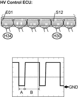
Item
Contents
Terminal
S12 (H30-13) - E01 (H34-7)
Equipment Setting
1V/DIV, 50μs/DIV
Condition
Ignition switch ON or READY-on state
- Standard:
- The waveform in the illustration can be measured.
- HINT:
- A and B in the DUTY waveform shown in the illustration vary depending on the cooling fan mode.
- Duty command value is influenced by variance in fan motors and the change of power supply voltage.
- Measure when the vehicle comes to a stop and an idling stop.
- A and B in the DUTY waveform shown in the illustration vary depending on the cooling fan mode.
|
|
||||
| OK | ||
|
||
| ||