Previous Next

DRIVE TRAIN


Drive Train

TRANSAXLE AND TRANSMISSION

Manual Transmission Assembly

REMOVAL AND INSTALLATION

1993-95 Miata 1.6L (B6-ZE) and 1994-97 1.8L (BPD) with M15M-D Transmission
  1. Disconnect the negative battery cable. Raise the vehicle and support it safely. Drain the transmission.
  2. Remove the shifter knob, and the center console. Remove the gearshift lever.
  3. Remove the engine undercover and the performance rod.
  4. Disconnect the exhaust pipe from the manifold. Remove the entire exhaust system as an assembly.
  5. Matchmark the driveshaft flange at the rear, and remove the driveshaft.
  6. Without disconnecting the hydraulic hose, remove the clutch release cylinder and set it aside. Disconnect the wiring and remove the starter.
  7. Disconnect the speedometer cable, and remove the wiring from the frame member.
  8. Support the transmission and differential with jacks. Remove the transmission-to-differential frame (also called the power plant frame or PPF) as follows:
    1. Remove the frame-to-transmission bracket.
    2. Remove the bolts from the underside of the frame at the differential end, noting their location. Pry out the spacer from the frame.
    3. Remove the differential mounting spacer from the underside of the differential.
    4. Insert a 14 x 1.5mm bolt through the frame hole, and turn it into the sleeve. Twist and pull the bolt downward.
    5. Install a 6 x 1mm bolt in the side hole to hold the sleeve, and remove the long bolt. Remove the short bolt.

      NOTE: Do not remove the spacers from the end of the PPF. Doing so will reduce the performance of the frame. If the spacers are removed, the PPF must be replaced as an assembly.

    6. Remove the transmission side bolts, and remove the frame member.
  9. Remove the bolts from the clutch housing, and slide the transmission back away from the engine. Lower the transmission from the vehicle.

    To install:

  10. Lightly lubricate the main shaft spline and the release bearing fork contact points with molybdenum grease and install the fork. Place a wood block on a floor jack and use it to tilt the engine up in front.
  11. Carefully guide the transmission into place, making sure the main shaft spline fits properly into the clutch disc. Start all the transmission retaining bolts by hand. Tighten them alternately, in several passes, to 48-65 ft. lbs. (64-89 Nm).
  12. Install the transmission-to-differential frame, and loosely install all the bolts. Torque the frame-to-transmission bolts, then the frame-to-differential bolts to 76-91 ft. lbs. (104-124 Nm). Install the bracket, and torque the bracket-to-transmission bolts to 27-40 ft. lbs. (37-54 Nm), the bracket-to-frame bolts to 77-91 ft. lbs. (104-124 Nm).

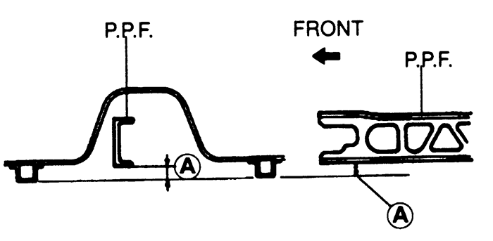
    NOTE: After the frame installation, position a straightedge between the body frame members on each side of the vehicle. Measure the distance between the bottom of the frame to the straightedge; it should be 2.403-2.797 in. (61-71mm). If the distance is not as specified, reposition the frame member at the transmission.

    Fig. 1:Measure distance A after installing the transmission-to-differential frame member -- 1993-95 Miata 1.6L (B6-ZE) and 1.8L (BPD) with M15M-D transmission

  13. Connect the speedometer cable and wiring, and install the starter,.
  14. Install the clutch release cylinder.
  15. Install the driveshaft, and torque the nuts to 22 ft. lbs. (30 Nm).
  16. Use a new gasket and install the exhaust system. Torque the nuts to 34 ft. lbs. (46 Nm).
  17. Install the performance rod and engine undercover.
  18. Lower the vehicle.
  19. Fill the transmission with the proper type and quantity of oil.
  20. Install the shift lever, rear console and the shift lever knob.
  21. Connect the negative battery cable.
  22. Verify proper operation of the transmission.
1993-95 RX7 1.3L (13B) with R15M-D Transmission
  1. Disconnect the negative battery cable. Raise and safely support the vehicle. Drain the transmission oil.
  2. Remove the shift lever knob and the console panel assembly. Remove the insulators and the shift lever.
  3. Remove the transmission undercovers.
  4. Remove the clutch slave cylinder bolts and hydraulic line bracket bolt. Secure the slave cylinder aside, without disconnecting the hydraulic line.
  5. Label and disconnect the electrical connectors to the starter. Remove the starter.
  6. Remove the center tunnel reinforcement. Disconnect the air injection pipe and remove the catalytic converter.
  7. Remove the front and rear tunnel reinforcements.
  8. Remove the cover plate from under the transmission tailshaft. Mark the position of the driveshaft on the rear axle flange and remove the driveshaft.
  9. Support the engine using engine support tool 49 G017 5A0 or equivalent. Support the differential with a jack.
  10. Remove the transmission-to-differential frame member.
  11. Label and disconnect the necessary electrical connectors. Remove the service hole covers from the transmission and remove the backup light switch.
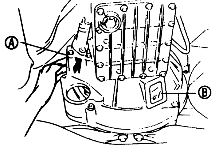
  12. Working through the service hole A, swing the clutch release fork so the release bearing is pushed and held toward the clutch pressure plate.
  13. Insert a small prybar through service hole B and into the space between the wedge collar and the release bearing. Pry and separate the release bearing from the clutch pressure plate.
  14. Swing the clutch release fork back and forth to make sure the release bearing and clutch pressure plate are separated.
  15. If Steps 12-14 do not work, gradually loosen the 6 clutch pressure plate bolts in a crisscross pattern, working through service hole B. Remove the bolts and separate the pressure plate from the flywheel.
  16. Support the transmission with a jack and remove the transmission-to-engine bolts. Carefully remove the transmission.
  17. If the transmission was removed as per Step 15, remove the wire ring from the release bearing and separate the release bearing from the clutch pressure plate.

    To install:

  18. If the clutch pressure plate was removed, proceed as follows:
    1. Install a new wedge collar on the pressure plate. Apply a small amount of grease to a new wire ring and install on the wedge collar.
    2. Clean the clutch disc splines and apply a small amount of molybdenum grease to the splines.
    3. Install the clutch disc on the flywheel and install a suitable alignment tool.
    4. Install the clutch pressure plate, aligning the dowel holes with the flywheel dowels. Install the bolts and gradually tighten to 19 ft. lbs. (25 Nm), in a crisscross pattern.
    5. Remove the clutch alignment tool.
  19. Coat the splines of the transmission input shaft with molybdenum grease.
  20. Raise the transmission into position and install the transmission-to-engine bolts. Tighten the bolts to 38 ft. lbs. (51 Nm).
  21. Working through service holeA , push the release cylinder end of the clutch release fork toward the transmission and connect the clutch release bearing to the clutch pressure plate.
  22. Swing the clutch release fork back and forth to make sure the clutch release bearing is connected to the clutch pressure plate. Push the release cylinder end of the clutch release fork toward the engine and make sure it does not move past the engine-transmission mating line.
  23. Install the service hole covers. Install the backup light switch and tighten to 25 ft. lbs. (34 Nm). Connect the electrical connectors.
  24. Position the jack under the differential so the differential is perfectly level. Install the transmission-to-differential frame member and hold in place with a new bolt and 8 new nuts.
  25. Tighten the frame-to-differential nuts to 130 ft. lbs. (176 Nm) and the frame-to-differential bolt to 68 ft. lbs. (93 Nm).
  26. Tighten the frame to transmission nuts to 130 ft. lbs. (176 Nm), tightening the upper nuts first.
  27. Remove the jack from under the differential. Lower the vehicle and remove the engine support tool.
  28. Raise and safely support the vehicle. Position a straightedge between the right and left floorpans and measure the distance between the bottom of the frame member and the straightedge. The distance should be 2.91 in. (74mm) minimum. If the distance is not correct, readjust the frame member.
  29. Install the driveshaft, aligning the marks made during removal. Tighten the bolts to 43 ft. lbs. (58 Nm).
  30. Install the cover under the transmission tailshaft. Install the front and rear tunnel reinforcements and tighten to 19 ft. lbs. (25 Nm).
  31. Install the catalytic converter, using new gaskets, and tighten the nuts to 65 ft. lbs. (89 Nm). Connect the air injection pipe.
  32. Install the center tunnel reinforcement and tighten the bolts to 19 ft. lbs. (25 Nm).
  33. Install the starter and tighten the bolts to 38 ft. lbs. (51 Nm). Connect the starter wiring.
  34. Install the clutch slave cylinder and tighten the bolts to 15 ft. lbs. (22 Nm).
  35. Install the transmission undercovers. Fill the transmission with the proper type and quantity of oil and lower the vehicle.
  36. Install the shift lever assembly and insulators. Install the console panel and the shift lever knob. Connect the negative battery cable.
    Fig. 2:Service hole identification -- 1993-95 RX7 1.3L (13B) with R15M-D transmission

 
Previous Next