Previous Next

Manual Transaxle Assembly

REMOVAL AND INSTALLATION

1993-94 323, Protege and 1994 MX3 with F25MR, FA4A and G25MR Transmissions
  1. Properly relieve the fuel system pressure.
  2. Disconnect the battery cables and remove the battery and the battery tray. Raise and safely support the vehicle.
  3. Remove the splash shield(s) from under the vehicle and drain the engine and transaxle oil and the coolant.
  4. Remove the air cleaner assembly and resonance chamber, including the air flow meter and all of the ducting. Remove the oil dipstick.
  5. Remove the radiator hoses. If equipped with automatic transaxle, disconnect the oil cooler lines from the radiator. Disconnect the cooling fan and, if equipped, radiator switch electrical connectors and remove the radiator/cooling fan assembly.
  6. Disconnect the throttle and the speedometer cable.
  7. Label and disconnect the vacuum hoses and wiring.
  8. Disconnect the fuel supply and return hoses and the heater hoses.
  9. Disconnect the exhaust pipe from the manifold. On 4WD vehicles, remove the exhaust manifold. If equipped, remove the water inlet pipe and gasket.
  10. Without disconnecting the hydraulic hoses, remove the power steering pump and hang it from the body with wire.
  11. Without disconnecting the refrigerant lines, remove the air conditioning compressor and hang it from the body with wire.
  12. If equipped with manual transaxle, disconnect the clutch cable and shift control rod. If equipped with hydraulic clutch, remove the slave cylinder from the transaxle without disconnecting the hydraulic line.
  13. If equipped with automatic transaxle, disconnect the shift control cable.
  14. Remove the nuts and disconnect the tie rod ends from the steering knuckles. Disconnect the stabilizer bar from the lower control arms.
  15. Attach an engine lifting chain to the engine lifting eyes. Attach the chain to a suitable engine hoist and raise the hoist until there is tension on the chain.
  16. Remove the engine mount nuts and the engine mount member bolts and nuts and remove the engine mount member. On 4WD vehicles, remove the front transaxle mount.

    NOTE: Be careful so the engine does not fall when removing the engine mount member.

  17. Remove the pinch bolts from the steering knuckle and pry the control arm down to slip lower ball joint out of the knuckle.
  18. If equipped, remove the bolts from the right side intermediate shaft support and, using a suitable prybar, pry the intermediate shaft from the transaxle. Insert a suitable prybar between the inner CV-joint and transaxle case and carefully pry the inner CV-joints out of the transaxle. Suspend the halfshafts with wire.
  19. Remove the dynamic damper from the right side engine mount, if equipped. Remove the engine/transaxle mount nuts/bolts and right engine and, if equipped, left transaxle mounts. Carefully lift the engine/transaxle assembly from the vehicle.
  20. Properly support the engine/transaxle assembly. Remove the intake manifold bracket, starter, torque converter nuts, stiffener, if equipped and No. 2 engine mount. Disconnect the throttle cable.
  21. Remove the transaxle mounting bolts and separate the transaxle from the engine.

    To install:

  22. Attach the transaxle to the engine and install the transaxle-to-engine bolts. Install the torque converter nuts and tighten to 25-36 ft. lbs. (34-49 Nm).
  23. Connect the throttle cable. Install the No. 2 engine mount, stiffener, if equipped, starter and intake manifold bracket.
  24. Install the engine mount member and tighten the bolts/nuts to 47-66 ft. lbs. (64-89 Nm).
  25. Carefully lower the engine/transaxle assembly into the engine compartment and align the engine mount bolts with the engine mount member mounting holes. Install the mount-to-mount member nuts and tighten to 27-38 ft. lbs. (37-52 Nm).
  26. Install the right side engine mount. Tighten the mount-to-engine nut(s) to 54-76 ft. lbs. (74-103 Nm) on 1993 vehicles. Tighten the mount through-bolt to 49-69 ft. lbs. (67-93 Nm) on 1993 vehicles.
  27. On 1993 vehicles, install the dynamic damper, to the right side mount and tighten to 41-59 ft. lbs. (55-80 Nm).
  28. If equipped, install the left side transaxle mount. On 1993 vehicles, loosely install the mount-to-transaxle nuts and align the mount bracket holes with the body holes. Install the mount-to-body bolts and tighten, in sequence, to 32-45 ft. lbs. (43-61 Nm). Tighten the mount-to-transaxle nuts to 49-69 ft. lbs. (67-93 Nm).
  29. Install new circlips on the inner CV-joint stub shafts and, if equipped, intermediate shaft. Grease the shaft splines and install the halfshaft/intermediate shaft into the transaxle.
  30. If equipped, install the right intermediate shaft support bolts and tighten, in sequence, to 31-46 ft. lbs. (42-62 Nm).
  31. Install the lower ball joint and torque the clamping bolt to 43 ft. lbs. (59 Nm). Install the tie rod ends and torque the nut to 42 ft. lbs. (57 Nm), then tighten as required to install a new cotter pin.
  32. Attach the stabilizer bar and tighten the nuts so there is 34 in. (19mm) of thread showing above the nut.
  33. Connect the extension bar and shift control rod. Connect the clutch cable or install the hydraulic slave cylinder, as necessary.
  34. Install a new gasket and connect the exhaust pipe to the manifold. Use new self-locking nuts and torque to 34 ft. lbs. (46 Nm).
  35. Connect the wiring and all heater, fuel and vacuum hoses.
  36. Install the air conditioner compressor and power steering pump, if equipped.
  37. Install the radiator/cooling fan assembly and connect the radiator hoses and the necessary electrical connectors.
  38. Connect the accelerator and speedometer cables.
  39. Install the battery tray assembly and battery. Install the air cleaner and air flow meter assembly and all the ducting. Connect the air flow sensor connector.
  40. Install the splash shield(s).
  41. Fill the engine and the transaxle with the proper types and quantities of oil. Fill the cooling system.
  42. Connect the negative battery cable, start the engine and check for leaks. Check the ignition timing and the idle speed. Check all fluid levels.
1995 Protege with G25M-R Transaxle and 1995-97 Protege with F25M-R Transaxle
  1. Drain the transaxle oil.
  2. Remove the battery box and the battery.
  3. Remove the air cleaner assembly.
  4. Remove the battery carrier.
  5. Disconnect the back-up light switch and remove the bracket.
  6. Disconnect the neutral switch connector and the vehicle speedometer sensor connector.
  7. Remove the harness bracket.
  8. Remove the wheels.
  9. Remove the splash shield.
  10. Remove the transverse member.
  11. Remove the extension bar and the change control rod.
  12. Disconnect the tie-rod ends.
  13. Remove the stabilizer control link.
  14. Remove the driveshafts and the joint shaft.
  15. Remove the intake manifold bracket.
  16. Remove the starter.
  17. Support the engine and remove the engine mounting member.
  18. Remove the rear engine/trans mount.
  19. Remove the front engine/trans mount.
  20. Remove the clutch release cylinder.
  21. Remove the side engine/trans mount.
  22. Support the transaxle on a jack and remove the trans mounting bolts.
  23. Remove the transaxle.

    To install:

  24. Place the transaxle into position and install the mounting bolts. Torque to 48-65 ft. lbs. (64-89 Nm).
  25. Remove the support jack.
  26. Install the side mount. Torque the body side nuts and bolts to 32-44 ft. lbs. (44-60 Nm). Torque the trans side nuts to 50-68 ft. lbs. (67-93 Nm).
  27. Install the clutch release cylinder.
  28. Install the front mount, loosely tighten the mount nut and bolt.
  29. Install the rear mount, align and set all bolts then torque to 50-68 ft. lbs. (67-93 Nm).
  30. Install the engine mounting member. Torque the four outer nuts and bolts to 50-65 ft. lbs. (67-89 Nm) and the two remaining nuts to 28-38 ft. lbs. (38-51 Nm).
  31. Torque the front mount nut and bolt to 50-68 ft. lbs. (67-93 Nm).
  32. Install the starter.
  33. Install the manifold bracket.
  34. Install the joint shaft and the driveshafts.
  35. Install the stabilizer control link.
  36. Connect the tie-rod ends.
  37. Connect the change control rod and the extension bar.
  38. Install the transverse member.
  39. Install the splash shield.
  40. Install the wheels.
  41. Install the harness bracket.
  42. Install the vehicle speedometer sensor connector and the neutral switch connector.
  43. Install the back-up light switch connector bracket and the switch.
  44. Install the battery carrier.
  45. Install the air cleaner assembly.
  46. Install the battery and battery box.
  47. Fill the trans with the proper fluid.
  48. Check for proper clutch operation.
1993-95 MX3 with F25M, F25MR, F2SM-R and G25MR Transaxles
  1. Relieve the fuel system pressure and disconnect the negative battery cable. Raise and safely support the vehicle and drain the fluid from the transaxle.
  2. Remove the wheel and tire assemblies and the splash shield.
  3. Remove the resonance duct and the air cleaner assembly.
  4. Disconnect the positive battery cable and remove the battery and battery tray.
  5. Remove the starter and the wiring harness bracket. Disconnect the fuel lines and remove the fuel filter.
  6. Label and disconnect the connectors for the neutral switch, backup light switch and speedometer sensor.
  7. Remove the mounting bolts and line clip and position the clutch slave cylinder aside without disconnecting the hydraulic line.
  8. Remove the transverse member and the front exhaust pipe/converter assembly.
  9. Disconnect the extension bar and shift control rod from the transaxle.
  10. Remove the cotter pins and nuts and separate the tie rod ends from the knuckles. Disconnect the stabilizer links from the lower control arms.
  11. Remove the halfshafts and the intermediate shaft.
  12. Support the engine using engine support tool 49 G017 5A0 or equivalent. Remove the bolts/nuts and remove the engine mount member.
  13. Remove the left side transaxle mount and the transaxle inspection plate.
  14. Loosen the engine support tool and lean the engine toward the transaxle. Support the transaxle with a jack. Remove the transaxle mounting bolts and carefully remove the transaxle.

    To install:

  15. Raise the transaxle into position and install the transaxle-to-engine bolts. Tighten to 66 ft. lbs. (89 Nm) on the 1.6L engine and 73 ft. lbs. (99 Nm) on the 1.8L engine.
  16. Install the transmission inspection plate and tighten the bolts to 38 ft. lbs. (52 Nm).
  17. Loosely tighten the left side transaxle mount bolts.
  18. Install the engine mount member, aligning the front and rear transaxle mount stud bolts. Install the mount member-to-mount nuts and tighten to 38 ft. lbs. (52 Nm) and the mount member bolts/nuts to the body, and tighten to 66 ft. lbs. (89 Nm).
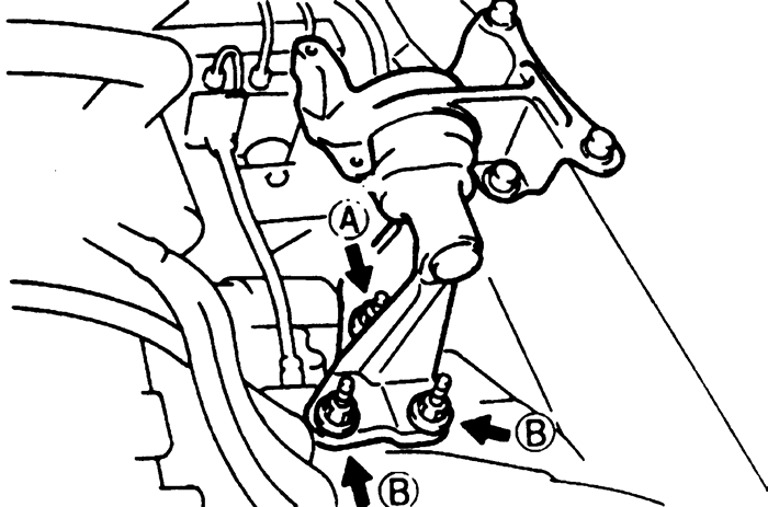
    Fig. 1:Number four engine mount bolt locations (1.8L only) -- 1993-95 MX3 with F25M, F25MR, F2SM-R and G25MR transaxles

  19. Tighten left side transaxle mount-to-transaxle nut A to 69 ft. lbs. (93 Nm) and nuts B to 30 ft. lbs. (40 Nm). Remove the engine support tool.
  20. Install the halfshafts and joint shaft.
  21. Connect the stabilizer bar link to the lower control arm and tighten the nut to 45 ft. lbs. (61 Nm). Connect the tie rod end to the steering knuckle and tighten the nut to 42 ft. lbs. (57 Nm). Install a new cotter pin.
  22. Connect the extension bar to the transaxle and tighten the bolt to 38 ft. lbs. (52 Nm). Connect the shift control rod and tighten the bolt to 17 ft. lbs. (23 Nm).
  23. Install the exhaust pipe, using new gaskets. Tighten the manifold flange nuts to 38 ft. lbs. (52 Nm).
  24. Install the transverse member and tighten the bolts to 93 ft. lbs. (127 Nm).
  25. Connect the electrical connectors. Install the fuel filter and connect the fuel lines.
  26. Install the starter and the wiring harness bracket.
  27. Install the battery tray and battery.
  28. Install the air cleaner assembly and the resonance duct. Install the splash shield and the wheel and tire assemblies.
  29. Fill the transaxle with the proper type and quantity of oil.
  30. Lower the vehicle and connect the battery cables. Start the engine and check for leaks and proper transaxle operation.
1993-97 626 and MX6 with G25M-R Transaxle
  1. Disconnect the battery cables and remove the battery and battery tray. Raise and safely support the vehicle. Drain the transaxle fluid.
  2. Remove the ducts and the air cleaner assembly.
  3. If equipped with 2.5L engine, remove the starter.
  4. Label and disconnect the electrical connectors for the neutral switch, backup light switch and vehicle speed sensor. Disconnect the ground wires.
  5. Remove the fuel filter mounting nuts and position the filter aside, leaving the fuel lines attached. Remove the wiring harness bracket.
  6. Remove the mounting bolts and the hydraulic line clips, then position the clutch slave cylinder aside, leaving the hydraulic line attached.
  7. Remove the wheel and tire assemblies and the splash shields. Remove the transverse member.
  8. If equipped with 2.5L engine, disconnect the oxygen sensor connectors and remove the front exhaust pipe/catalytic converter assembly.
  9. Disconnect the extension bar and shift control rod from the transaxle.
  10. Remove the pinch bolts from the steering knuckles. Pry the lower control arms down to separate the ball joints from the knuckles.
  11. Remove the cotter pins and nuts and separate the tie rod ends from the knuckles. Remove the nuts and disconnect the stabilizer links from the lower control arms.
  12. Remove the brake hose clips from the struts, and (if equipped) remove the ABS speed sensor harness mounting nuts.
  13. Separate the right side halfshaft from the intermediate shaft using a hammer and brass drift. Pry the left side shaft from the transaxle using a prybar inserted between the transaxle and the inner CV-joint. Be careful not to damage the oil seal.
  14. Suspend the halfshafts with rope, in a level position. Insert plug tools 49 G030 455 or equivalent into the differential side gears to keep them from becoming mispositioned.
  15. Remove the intermediate/joint shaft.
  16. If equipped with 2.0L engine, remove the starter.
  17. Remove the engine mount rubber at the right side of the engine mount member. Remove the rear transaxle mount.
  18. Support the engine using engine support tool 49 G017 5A0 or equivalent. Remove the nuts and bolts and remove the engine mount member.
  19. If equipped with 2.5L engine, remove the transaxle housing inspection plate.
  20. Remove the left side transaxle mount.
  21. Loosen the engine support tool and lean the engine toward the transaxle. Support the transaxle on a jack and remove the transaxle mounting bolts. Carefully remove the transaxle from the vehicle.
  22. Remove the front transaxle mount.

    To install:

  23. Install the front transaxle mount and tighten the mount-to-transaxle bolts to 44 ft. lbs. (60 Nm). Loosely tighten the mount through-bolt and nut.
  24. Raise the transaxle into position and install the transaxle mounting bolts. If equipped with 2.5L engine, install the inspection cover. Tighten the mounting bolts to the proper torque values.
  25. Loosely tighten the left side transaxle mount bolts and nuts.
  26. Use the engine support tool to make sure the transaxle bolt holes and the rear transaxle mount are aligned. Install the bolts and tighten to 68 ft. lbs. (93 Nm).
  27. Install the engine mount member, making sure the engine mount rubbers are properly installed. Tighten the mount member-to-body bolts/nuts to 68 ft. lbs. (93 Nm) and the front transaxle mount nuts to 77 ft. lbs. (104 Nm).
  28. Tighten the front transaxle mount through-bolt and nut to 86 ft. lbs. (116 Nm).
  29. Tighten the left side transaxle mount bolts and nut to 68 ft. lbs. (93 Nm) and remove the engine support tool.
  30. Install the engine mount rubber on the right side of the mount member and tighten the bolts to 44 ft. lbs. (60 Nm).
  31. If equipped with 2.0L engine, install the starter.
  32. Remove the plug tool from the differential side gear. Install the intermediate/joint shaft into the transaxle. Install the support bearing to the engine and tighten the bolts, in sequence, to 45 ft. lbs. (61 Nm).
  33. Remove the plug from the other differential side gear. Install a new circlip on the halfshaft with end gap facing upward. Install the halfshaft into the transaxle, being careful not to damage the seal. Make sure the circlip seats in the differential side gear, by pulling out on the shaft; it must not pull out.
  34. Install a new circlip on the end of the other halfshaft and connect it to the intermediate shaft.
  35. Connect the lower ball joints to the steering knuckles. Install the pinch bolts and tighten to 43 ft. lbs. (58 Nm).
  36. Connect the stabilizer links to the lower control arms and tighten the nuts to 39 ft. lbs. (53 Nm). Connect the tie rod ends to the steering knuckles and tighten the nuts to 32 ft. lbs. (44 Nm). Install new cotter pins.
  37. Connect the shift control rod to the transaxle and tighten the bolt to 18 ft. lbs. (25 Nm). Connect the extension bar and tighten the nut to 38 ft. lbs. (51 Nm).
  38. If equipped with 2.5L engine, install the exhaust pipe, using new gaskets. Tighten the exhaust manifold flange nuts to 38 ft. lbs. (51 Nm). Connect the oxygen sensor connectors.
  39. Install the transverse member and tighten the bolts to 96 ft. lbs. (131 Nm).
  40. Install the splash shields and the wheel and tire assemblies.
  41. Install the clutch slave cylinder and tighten the bolts to 16 ft. lbs. (22 Nm). Install the wiring harness bracket and tighten the bolts to 130 inch lbs. (14 Nm).
  42. Install the fuel filter mounting nuts and tighten to 95 inch lbs. (11 Nm). Connect the grounds and electrical connectors.
  43. If equipped with 2.5L engine, install the starter.
  44. Install the air cleaner assembly and air ducts. Install the battery tray and battery.
  45. Fill the transaxle with the proper type and quantity of fluid and lower the vehicle.
  46. Connect the battery cables and start the engine. Check for leaks and for proper transaxle operation.
 
Previous Next