Previous Next

REMOVAL AND INSTALLATION

1993-94 323, MX3 and Protege
  1. Raise and safely support the vehicle. Remove the front wheel and tire assemblies.
  2. Uncrimp the tab on the center locknut and remove the locknut. Discard the old locknut.
  3. Remove the caliper assembly from the knuckle. Do not disconnect the brake lines. Support the caliper with a piece of wire. Do not allow the caliper to hang by the hose at any time. Remove the brake disc.
  4. Remove the tie rod end cotter pin and remove the tie rod end nut. Using Mazda tool 49 0118 850C or equivalent, press the tie rod end out of the knuckle assembly.
  5. Remove the stabilizer upper nuts and remove the stabilizer link bolt.
  6. Remove the outer lower arm to ball joint mounting bolt and nut. Separate the lower arm from the knuckle assembly.
  7. Remove the ABS speed sensor if so equipped.
  8. Using a plastic mallet, tap the driveshaft free of the knuckle assembly. Remove the knuckle assembly.
  9. Clamp the knuckle in a vise with protected jaws.
  10. Remove the inner oil seal from the knuckle.
  11. Use Mazda hub puller tools 49 G033 102, 49 G033 104 and 49 G033 105 or equivalent, and remove the front wheel hub from the knuckle assembly.
  12. Remove the bearing inner race from the front wheel hub.
  13. Remove the retaining ring from within the knuckle and using the hub puller tools, press the front wheel bearing from the knuckle.
  14. Remove the brake dust shield.
  15. Clean and inspect all parts but do not wash or clean the wheel bearing. The bearing must be replaced.
  16. Using Mazda press tools 49 G033 107 and 49 H026 103 or equivalent, install a new dust shield cover assembly to the knuckle.
  17. Using the press tools, press a new wheel bearing into the knuckle assembly.
  18. Install the wheel bearing retaining ring, and install a new oil seal using installation tool 49 V001 795.
  19. Install the front wheel hub by using the Mazda press tools or equivalent.
  20. Install the bearing/hub and knuckle assembly in place. Loosely tighten the knuckle to shock absorber bolt.
  21. Install the lower arm ball joint to the knuckle and tighten the nut to 27-40 ft. lbs. (36-54 Nm).
  22. Install the driveshaft to the knuckle assembly.
  23. Install the stabilizer control link and tighten the nuts so that there is 0.71-0.87 inches (18.1-22.1mm) of thread exposed. Torque the top link nut to 12-17 ft. lbs. (16-23 Nm).
  24. If equipped with ABS, install the wheel speed sensor and tighten the bolts to 12-17 ft. lbs. (16-23 Nm).
  25. Connect the tie rod ends to the knuckle and tighten the nuts to 31-42 ft. lbs. (42-57 Nm). Replace the cotter pins.
  26. Install a new wheel hub locknut and tighten the locknut to 174-235 ft. lbs. (235-319 Nm).
  27. Check the end play of the wheel bearing by installing a dial indicator against the wheel hub and tire to move the brake disc back and forth. There should be no more than 0.0079 inch (0.2mm) of freeplay present.
  28. Stake the locknut into place by bending it into the groove.
  29. Install the brake caliper(s) and tighten the bolts to 58-72 ft. lbs. (78-98 Nm).
  30. Install the front wheels and lower the vehicle.
  31. With the vehicle lowered check all of the bolts and re-torque as is necessary.
  32. Inspect the front end alignment and adjust as is necessary.
1995 MX3 and 1995-97 Protege
  1. Raise and safely support the vehicle. Remove the front wheels.
  2. Uncrimp the tab on the center locknut and remove the locknut. Discard the old locknut.
  3. Remove the caliper assembly from the knuckle. Do not disconnect the brake lines. Support the caliper with a piece of wire. Do not allow the caliper to hang by the hose at any time. Remove the brake disc.
  4. Remove the ABS speed sensor if so equipped.
  5. Remove the tie rod end cotter pin and remove the tie rod end nut. Using Mazda tool 49 T028 3AO or equivalent, press the tie rod end out of the knuckle assembly.
  6. Remove the outer lower arm to ball joint mounting bolt and nut. Separate the lower arm from the knuckle assembly.
  7. Using a plastic mallet, tap the knuckle assembly free of the driveshaft. Remove the knuckle assembly.
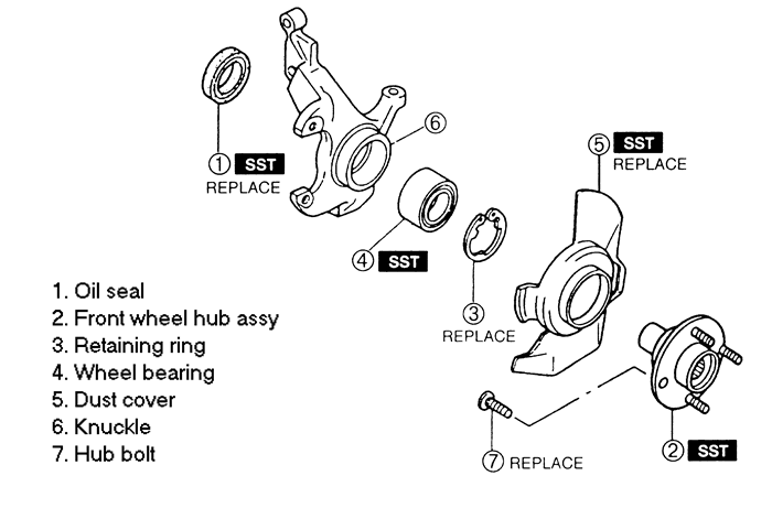
    Fig. 1: Steering knuckle and hub disassembly (exploded view) -- 1995 MX3 and 1995-97 Protege

  8. Clamp the knuckle in a vise with protected jaws.
  9. Remove the inner oil seal from the knuckle.
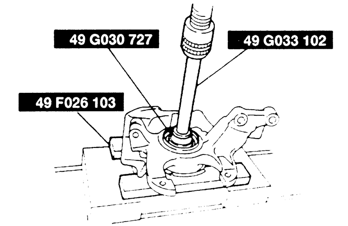
  10. Use Mazda hub-puller tools 49 F026 103, 49 G030 727 and 49 G033 102 or equivalent, and remove the front wheel hub from the knuckle assembly.
    Fig. 2:Removing the hub from the steering knuckle -- 1995 MX3 and 1995-97 Protege

  11. Remove the bearing inner race from the front wheel hub.

    NOTE: If the bearing inner race still remains on the hub assembly, grind a section of the bearing inner race until about 0.02 inch (0.50 mm) remains. Remove with a chisel.

  12. Remove the retaining ring from within the knuckle and using the wheel bearing removal tools (49 F027 005 and 49 F027 003 or equivalent), press the front wheel bearing from the knuckle.
  13. Clean and inspect all parts but do not wash or clean the wheel bearing. .
  14. Using the press tools, press a new wheel bearing into the knuckle assembly.
  15. Install the wheel bearing retaining ring.
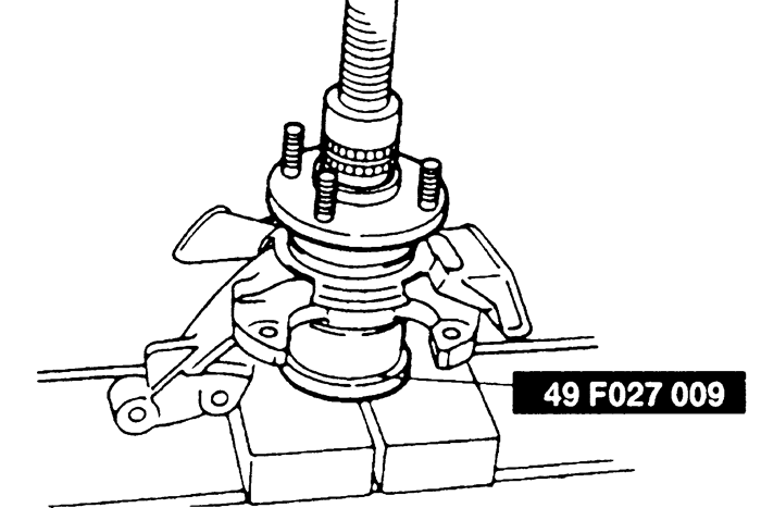
  16. Install the front wheel hub by using the Mazda press tools 49 G033 102 and 49 F027 009 or equivalents.
    Fig. 3:Assembling the hub to the knuckle -- 1995 MX3 and 1995-97 Protege

  17. Install a new oil seal using installation tool 49 V001 795 and a hammer. Tap the oil seal in evenly until the special tool contacts the steering knuckle. Coat the lip of the oil seal with grease.
  18. Install the bearing/hub and knuckle assembly in place. Loosely tighten the knuckle to shock absorber bolt.
  19. Install the lower arm ball joint to the knuckle and tighten the nut to 33-43 ft. lbs. (44-58 Nm).
  20. Install the driveshaft to the knuckle assembly.
  21. If equipped with ABS, install the wheel speed sensor and tighten the bolts to 12-17 ft. lbs. (16-23 Nm).
  22. Connect the tie rod end to the knuckle and tighten the nut to 32-41 ft. lbs. (43-56 Nm). Replace the cotter pin.
  23. Install a new wheel hub locknut and tighten the locknut to 174-235 ft. lbs. (235-319 Nm).
  24. Check the end play of the wheel bearing by installing a dial indicator against the wheel hub and tire to move the brake disc back and forth. There should be no more than 0.002 inch (0.05mm) of freeplay present.
  25. Stake the locknut into place by bending it into the groove.
  26. Install the brake caliper(s) and tighten the bolts to 29-36 ft. lbs. (40-49 Nm).
  27. Install the front wheels and lower the vehicle.
  28. With the vehicle lowered check all of the bolts and re-torque as necessary.
  29. Inspect the front end alignment and adjust as is necessary.
1993-97 626 and MX6
  1. Raise and safely support the vehicle. Remove the front wheel and tire assemblies.
  2. Uncrimp the tab on the center locknut and remove the locknut. Discard the old locknut.
  3. Remove the caliper assembly from the knuckle. Do not disconnect the brake lines. Support the caliper with a piece of wire. Do not allow the caliper to hang by the hose at any time. Remove the brake disc.
  4. Remove the ABS speed sensor if so equipped.
  5. Remove the tie rod end cotter pin and remove the tie rod end nut. Using Mazda tool 49 T028 3AO or equivalent, press the tie rod end out of the knuckle assembly.
  6. Remove the stabilizer upper nuts and remove the stabilizer link bolt.
  7. Remove the outer lower arm to ball joint mounting bolt and nut. Separate the lower arm from the knuckle assembly.
  8. Using a plastic mallet, tap the knuckle assembly free of the driveshaft. Remove the knuckle assembly.
  9. Clamp the knuckle in a vise with protected jaws.
  10. Remove the inner oil seal from the knuckle.
  11. Use Mazda hub puller tools 49 F026 103 and 49 G033 105 or equivalent, and remove the front wheel hub from the knuckle assembly.
  12. Remove the bearing inner race from the front wheel hub.

    NOTE: If the bearing inner race still remains on the hub assembly, grind a section of the bearing inner race until about 0.02 inch (0.50 mm) remains. Remove with a chisel.

  13. Remove the retaining ring from within the knuckle and using the wheel bearing removal tools (49 G033 106 and 49 G033 102 or equivalent), press the front wheel bearing from the knuckle.
  14. Clean and inspect all parts but do not wash or clean the wheel bearing.
  15. Using the press tools, press a new wheel bearing into the knuckle assembly.
  16. Install the wheel bearing retaining ring.
  17. Install the front wheel hub by using the Mazda press tools 49 G033 105 and 49 F027 009 or equivalent.
  18. Install a new oil seal using installation tool 49 V001 795 and a hammer. Tap the oil seal in evenly until the special tool contacts the steering knuckle. Coat the lip of the oil seal with grease.
  19. Install the bearing/hub and knuckle assembly in place. Loosely tighten the knuckle to shock absorber bolt.
  20. Install the lower arm ball joint to the knuckle and tighten the nut to 26-41 ft. lbs. (35-56 Nm).
  21. Install the driveshaft to the knuckle assembly.
  22. Install the stabilizer control link and tighten the nuts so that there is 0.71-0.87 inches (18.1-22.1mm) of thread exposed. Torque the top link nut to 12-17 ft. lbs. (16-23 Nm).
  23. If equipped with ABS, install the wheel speed sensor and tighten the bolts to 12-17 ft. lbs. (16-23 Nm).
  24. Connect the tie rod ends to the knuckle and tighten the nuts to 24-32 ft. lbs. (32-44 Nm). Replace the cotter pin.
  25. Install a new wheel hub locknut and tighten the locknut to 174-235 ft. lbs. (235-319 Nm).
  26. Check the end play of the wheel bearing by installing a dial indicator against the wheel hub and tire to move the brake disc back and forth. There should be no more than 0.0079 inch (0.2mm) of freeplay present.
  27. Stake the locknut into place by bending it into the groove.
  28. Install the brake caliper(s) and tighten the bolts to 58-72 ft. lbs. (78-98 Nm).
  29. Install the front wheels and lower the vehicle.
  30. With the vehicle lowered check all of the bolts and re-torque as is necessary.
  31. Inspect the front end alignment and adjust as is necessary.
1993-95 929
  1. Remove the dust cap. Unstake and loosen the locknut.
  2. Raise and safely support the vehicle. Remove the wheel and tire assembly.
  3. Remove the brake caliper and suspend it from the coil spring.
  4. Remove the disc brake rotor.
  5. Remove and discard the hub nut. Remove the wheel hub and bearing assembly. The wheel hub and bearing cannot be disassembled.

    To install:

  6. Install the hub over the spindle. Loosely install a new hub nut.
  7. Install the brake rotor and the disc brake caliper. Install the wheel and tire assembly, and lower the vehicle.
  8. When the vehicle is on the ground, tighten the hub nut. Tighten to 131-173 ft. lbs. (177-235 Nm).
  9. Install the dust cap.
1995-97 Millenia
  1. Raise and safely support the vehicle.
  2. Lock the hub by having a helper apply the brakes firmly. Remove the locknut.
  3. Remove the brake caliper assembly and disc plate.
  4. Disconnect the ABS wheel speed sensor cable mounting bolts.
  5. Disconnect the tie-rod end, upper leading link and upper lateral link.
  6. Remove the lower arm ball joint.
  7. Remove the front wheel hub and steering knuckle as an assembly.
  8. Press out the wheel hub from the knuckle. Grind out a section of the bearing inner race until approx. 0.020 in. (0.5 mm) remains. Then remove it with a chisel.
  9. Remove the oil seal from the knuckle.
  10. Remove the snapring and press out the wheel bearing using a press.
  11. Matchmark the knuckle and dust cover and remove the dust cover.

    To install:

  12. Install the dust cover to the knuckle.
  13. Press the wheel bearing onto the knuckle. Install the snapring.
  14. Press the hub assembly onto the knuckle.
  15. Install a new oil seal.
  16. Replace the knuckle/hub assembly to the vehicle and install the lower arm ball joint. Torque the ball joint mounting bolts to 58-86 ft. lbs. (79-116 Nm). Torque the ball joint nut to 86-115 ft. lbs. (116-156 Nm).
  17. Connect the upper lateral link ball joint and torque the nut to 41-59 ft. lbs. (55-80 Nm).
  18. Connect the upper leading link ball joint and torque the nut to 28-38 ft. lbs. (38-51 Nm).
  19. Connect the tie-rod end and torque the nut to 41-59 ft. lbs. (55-80 Nm).
  20. Install the ABS wheel speed sensor and torque the bolts to 14-18 ft. lbs. (19-25 Nm).
  21. Install the disc plate and caliper assembly.
  22. Install a NEW locknut and torque to 174-235 ft. lbs. (236-318 Nm).
1993-97 Miata
  1. Remove the dust cap. Unstake and loosen the locknut.
  2. Raise and safely support the vehicle. Remove the wheel and tire assembly.
  3. Remove the brake caliper and suspend it from the coil spring.
  4. Remove the disc brake rotor.
  5. Remove and discard the locknut. Remove the wheel hub and bearing assembly. The wheel hub and bearing cannot be disassembled.

    To install:

  6. Install the hub over the spindle. Loosely install a new locknut.
  7. Install the brake rotor and the disc brake caliper. Install the wheel and tire assembly, and lower the vehicle.
  8. When the vehicle is on the ground, tighten the hub nut. Tighten to 159 ft. lbs. (216 Nm).
  9. Install the dust cap.
1993-95 RX7
  1. Raise and safely support the vehicle. Remove the front wheel and tire assemblies.
  2. Uncrimp the tab on the center locknut and remove the locknut. Discard the old locknut.
  3. Remove the caliper assembly from the knuckle. Do not disconnect the brake lines. Support the caliper with a piece of wire. Do not allow the caliper to hang by the hose at any time. Remove the brake disc.
  4. Remove the tie rod end cotter pin and remove the tie rod end nut. Press the tie rod end out of the knuckle assembly.
  5. Remove the stabilizer upper nuts and remove the stabilizer link bolt.
  6. Remove the outer lower arm to ball joint mounting bolt and nut. Separate the lower arm from the knuckle assembly.
  7. Remove the ABS speed sensor if so equipped.
  8. Using a plastic mallet, tap the driveshaft free of the knuckle assembly. Remove the knuckle assembly.
  9. Clamp the knuckle in a vise with protected jaws.
  10. Remove the inner oil seal from the knuckle.
  11. Remove the front wheel hub from the knuckle assembly.
  12. Remove the bearing inner race from the front wheel hub.
  13. Remove the retaining ring from within the knuckle and using the hub puller tools, press the front wheel bearing from the knuckle.
  14. Remove the brake dust shield.

    To install:

  15. Clean and inspect all parts but do not wash or clean the wheel bearing. The bearing must be replaced.
  16. Install a new dust shield cover assembly to the knuckle.
  17. Press a new wheel bearing into the knuckle assembly.
  18. Install the wheel bearing retaining ring, and install a new oil seal.
  19. Install the front wheel hub.
  20. Install the bearing/hub and knuckle assembly in place. Loosely tighten the knuckle to shock absorber bolt.
  21. Install the lower arm ball joint to the knuckle and tighten the nut to 27-40 ft. lbs. (36-54 Nm).
  22. Install the driveshaft to the knuckle assembly.
  23. Install the stabilizer control link and tighten the nuts so that there is 0.71-0.87 inches (18.1-22.1mm) of thread exposed. Torque the top link nut to 12-17 ft. lbs. (16-23 Nm).
  24. If equipped with ABS, install the wheel speed sensor and tighten the bolts to 12-17 ft. lbs. (16-23 Nm).
  25. Connect the tie rod ends to the knuckle and tighten the nuts to 31-42 ft. lbs. (42-57 Nm). Replace the cotter pins.
  26. Install a new wheel hub locknut and tighten the locknut to 174-235 ft. lbs. (235-319 Nm).
  27. Check the end play of the wheel bearing by installing a dial indicator against the wheel hub and tire to move the brake disc back and forth. There should be no more than 0.0079 inch (0.2mm) of freeplay.
  28. Stake the locknut into place by bending it into the groove.
  29. Install the brake caliper(s) and tighten the bolts to 58-72 ft. lbs. (78-98 Nm).
  30. Install the front wheels and lower the vehicle.
  31. With the vehicle lowered check all of the bolts and re-torque as is necessary.
  32. Inspect the front end alignment and adjust as is necessary.
 
Previous Next