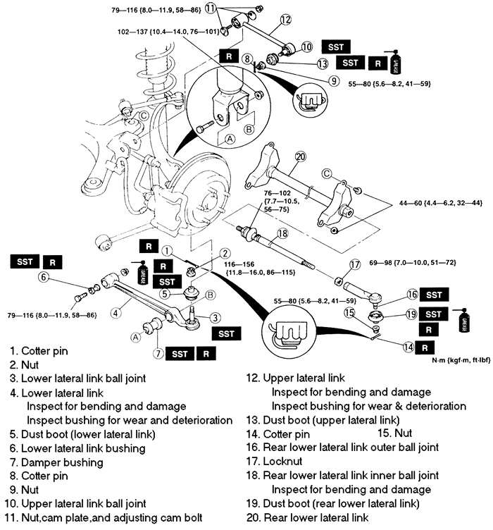
Raise and safely support the vehicle. Remove the
wheel and tire assembly.
Remove the cotter pin and loosen the front lower
lateral link ball joint nut. With the nut protecting the ball joint stud,
press out the stud with press tool 49 S231 575 or equivalent. Remove the
nut.
Remove the mounting bolt, and remove the lower lateral
link.
Remove the cotter pin and loosen the upper lateral
link ball joint nut. With the nut protecting the ball joint stud, press
out the stud with press tool 49 S231 575 or equivalent. Remove the nut.
Paint an alignment mark on the cam plate and crossmember
for assembly reference, before removing the upper lateral link bolt. Remove
the mounting bolt, and the upper lateral link.
Remove the cotter pin and loosen the rear lower lateral
link ball joint nut. With the nut protecting the ball joint stud, press
out the stud with press tool 49 0118 850C or equivalent. Remove the nut.
Remove the nuts, and remove the rear lower lateral link.
To install:
Install the rear lower lateral link and tighten the
nuts, in sequence, to 28-38 ft. lbs. (38-52 Nm).
Install the rear lower lateral link inner ball joint,
and tighten to 80-87 ft. lbs. (108-118 Nm).
Connect the rear lower lateral link outer ball joint
to the knuckle and tighten the nut to 37-47 ft. lbs. (50-64 Nm). Install
a new cotter pin.
Install the upper lateral link, and loosely tighten
the bolt. Connect the ball joint to the knuckle, and tighten the nut to
58-72 ft. lbs. (79-98 Nm). Install a new cotter pin.
Install the front lower lateral link and loosely
install the bolt. Connect the ball joint to the knuckle and tighten the
nut to 58-80 ft. lbs. (79-108 Nm). Install a new cotter pin.
Install the wheel and tire assembly and lower the
vehicle. With the vehicle at normal ride height, tighten the upper and
front lower lateral link bolts. Align the paint marks on the cam plate
and crossmember, and tighten the upper lateral link bolt to 86 ft. lbs.
(117 Nm). Tighten the lower lateral link bolt to the same specification.
Remove the cotter pin and nut and disconnect the
the lower lateral link ball joint stud from the rear knuckle assembly,
using the proper separator tool.
Remove the nut and bolt and remove the lower lateral
link from the rear crossmember.
If the lower lateral link ball joint is to be replaced, the lower lateral
link must be replaced.
To install:
Install the lower lateral link to the rear crossmember
with the nut and the bolt. Do not tighten the bolt and nut at this time.
Install a new dust boot and reinstall the lower lateral
link ball joint to the rear knuckle. Torque the ball joint nut to 86-115
ft. lbs. (116-156 Nm) and install a new cotter pin.
Install the tire and wheel assembly and safely lower
the vehicle.
Torque the lower lateral link to crossmember bolt
and nut to 58-86 ft. lbs. (79-116 Nm).
Remove the cotter pin and nut connecting the upper
lateral link to the knuckle. Remove the ball joint dust boot.
Remove the adjusting bolt, cam plate, and nut and remove the upper
lateral link from the crossmember mount.
To install:
Install the upper lateral link to the crossmember
mount with the adjusting bolt, cam plate, and locknut. Do not tighten
at this time.
Reinstall a new dust boot to the upper lateral link
and reattach the link to the knuckle with the nut. Torque the nut to 41-59
ft. lbs. (55-80 Nm). Install a new cotter pin.
Reinstall the tire and wheel assembly and safely
lower the vehicle.
Check the wheel alignment.
Torque the upper lateral link adjusting bolt and
nut to 58-86 ft. lbs. (79-116 Nm).
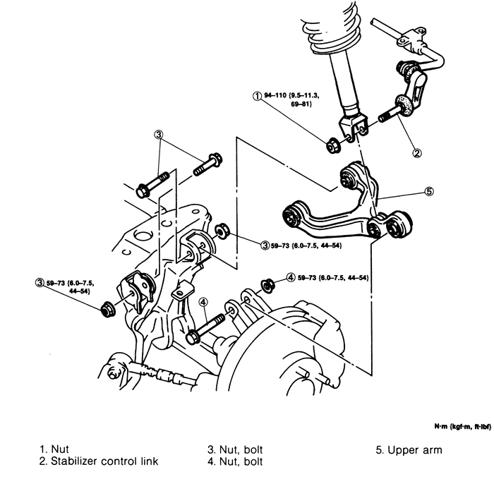
Fig. 2: Upper control arm removal and installation --
1993-95 RX7
Raise and safely support the vehicle and remove the
rear wheels.
Disconnect the stabilizer bar link and the lower
shock absorber mounting bolt from the control arm.
Remove the nuts, through-bolts and remove the control
arm.
Installation is the reverse of removal. Torque the
control arm through-bolts to 44-54 ft. lbs. (59-73 Nm). Torque the strut
mount bolt to 69-81 ft. lbs. (94-110 Nm).