Constantly be aware of the dangers involved when working on an automobile and
take the proper precautions. Use a safe chain hoist or floor crane of the proper
capacity. Work on level ground. Make sure the engine sling is secured properly
before lifting the engine. When working underneath a raised car always support
it on jackstands. Be careful not to spill brake fluid or engine coolant on painted
surfaces of the car body. Cover the front fenders if possible. Remember safety
is always the most important rule.
NOTE: On ff–1 and 1300G models, the engine and transaxle
must be removed as an assembly.
- Disconnect the battery cables, negative first.
- Remove the spare tire from the engine compartment.
- Remove the hood:
- Remove the horn multi-connector.
- Remove the nut securing the hood stay to the firewall.
- Make matchmarks on the hinges and body, and remove the hood hinge bolts
from the body, but leave the hinges fastened to the hood.
- Lift the hood clear of the body.
- Remove the two bolts which secure the front bumper to the bumper brackets.
- Remove the four screws (two on each side) which secure the grille and remove
it toward the front of the car.
- Remove the five bolts securing the hook lock assembly to the radiator support
and set it aside.
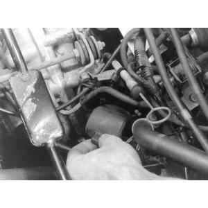
| Fig. 1: Common engine mount assembly
|
NOTE: Do not remove the cable from the hook lock.
- Remove the ten bolts securing the front roll pan and remove it in a downward
direction.
- Remove the hoses from the air cleaner and unfasten it from its brackets.
- Place a suitable container under the fuel line union to catch the gas,
and disconnect the hose at the union by removing the clip and pulling
the line off.
- Drain the engine and transaxle lubricant.
CAUTION
When draining the coolant, keep in mind that cats and dogs are attracted
by ethylene glycol antifreeze, and are quite likely to drink any that
is left in an uncovered container or in puddles on the ground. This
will prove fatal in sufficient quantity. Always drain the coolant into
a sealable container. Coolant should be reused unless it is contaminated
or several years old.
- Drain the coolant in the following manner:
- Remove the cap from the main radiator, after first pushing the button
on the expansion tank cap to allow any pressure to escape from the system.
- Place a clean container of a suitable size underneath the radiator drain
plug to save the coolant. Remove the drain plug.
- Move the container underneath and loosen, but do not remove, the left
and right drain plugs on the cylinder head.
- Remove all 3 radiator hoses from the engine.
- Disconnect the following wiring:
- Alternator multi-connector
- Starter wiring harness
- Thermostat harness
- Oil pressure switch connector
- High tension line at the coil
- Three blower motor connectors
- Distributor primary lead harness
- Two thermoswitch lines (at the sub-radiator)
- Remove the starter. Disconnect the heater duct from the blower housing.
- Remove the circlip which secures the inner and outer control cables, and
then detach the cables from the blower housing.
- Remove the front radiator support with the main radiator, sub–radiator,
shroud, blower motor and expansion tank as an assembly, in the following order:
NOTE: Do not separate the blower motor, itself, from the
radiator support because its assembly is quite difficult.
- Remove the two 8mm bolts which secure the blower housing.
- Remove the four screws and two bolts which secure the radiator support
to the headlamp bracket.
WARNING
Do not remove the center bolt.
- Slowly remove the assembly from the front of the car.
- Remove the hoses and leads from the windshield washer reservoir, and then
lift the reservoir out of its bracket.
- Disconnect both Double Offset Joints (DOJ) in the following manner:
- Apply the parking brake so that the drums can't turn.
- Remove the brake drum–to–double offset joint retaining bolts.
- Gently lower the joint and the axle shaft.
- Repeat for the other side.
- Disconnect the brake lines from both sides. Use a container to catch the
brake fluid, but do not reuse the fluid.
- Disconnect the following cables and linkages:
- Loosen, but don't remove, the screw on the carburetor throttle lever.
Detach the end of the cable, and pull the cable out.
- Remove the nut which secures the choke cable from its lever and loosen
the bracket retaining nut (6mm).
- Disconnect the speedometer cable from the speedometer head (from behind
the instrument cluster) and pull it out, working from the engine compartment.
- Disconnect the gear selector rod from inside the car.
- Disconnect the left and right parking brake cables from the turnbuckles
inside the car.
- Remove the clutch torque rod (ball stud) bolts on the side of the crossmember.
- Remove the bolts from the manifold pipe flanges and separate the downpipes
from the left and right manifolds. Be careful not to lose the insulators and
gaskets.
- Unfasten the brackets which secure the exhaust pipe to the floor pan and
remove the bolts which secure the exhaust pipe to the muffler hanger. Remove
the exhaust pipe.
- Disconnect the engine mount in the following order:
- Remove the securing nut from the shaft while holding the adjustment
nut.
- Remove the washer, cushion, pipe and tube.
- Unscrew the two retaining bolts and remove the bracket.
- Remove the left and right bolts from the rear support cushion which is located
on the transaxle housing. Leave the cushion attached to the transaxle case.
Be careful not to lose the washer.
- Remove the nut, spring washer, and washer from the front support cushion.
Leave the cushion attached to the engine.
- On station wagons, remove the horizontal damper by removing the front nut
and pulling the shaft rearward. Be careful not to lose any components.
- Check to be sure that everything which was supposed to have been removed
was, before going on to the next step.
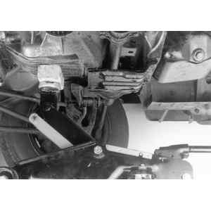
| Fig. 2: Engine mount alignment
|
| Fig. 3: Aligning the horizontal dampener
|
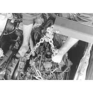
- Attach a chain hoist to the front and rear engine lifting hooks (hangers).
- Hoist the engine/transaxle assembly straight up, high enough so that the
brake drums clear the crossmember. Then carefully move the engine forward
so that the exhaust manifolds clear the crossmember and torsion bars.
| Fig. 4: Use a chain and hoist to remove the engine
from the vehicle
|
- Support the engine and transaxle in a suitable workstand.
To install:
- Using a hoist lower the engine and transaxle into the vehicle
- On station wagons, when installing the horizontal damper, be sure that the
larger of the two rubber cushions is compressed to 0.55 in. (13mm)
- Install the front support cushion washer, spring washer and nut.
- Install the support cushion washer(s) and the left and right bolts.
- When installing the engine mount, temporarily raise the adjusting nut so
that it is positioned about 1⁄4 in.
(6mm) below the nut above it. After installing the body bracket, lower the
adjusting nut until the middle cushion can be turned, while tightening the
bottom nut.
- Install the engine mount in the following order:
- Install the bracket and two retaining bolts
- Install the tube, pipe, cushion and the washer.
- Hold the adjustment nut and fasten the securing nut to the shaft.
Be sure to observe the following points during engine/transaxle installation:
- Tighten the engine mounts to the following specifications:
- Engine mount bolts: 18–20 ft. lbs. (24–27 Nm)
- Front cushion bolts: 18–25 ft. lbs. (24–33 Nm)
- Rear cushion bolts (3): 18–25 ft. lbs. (24–33 Nm)
- Rear cushion side bolt: 22–29 ft. lbs. (29–39 Nm)
- Install the exhaust pipe and fasten the bolts which secure the exhaust pipe
to the muffler hanger. Fasten the brackets which secure the exhaust pipe to
the floor pan. Install the insulators and gaskets, engage the downpipes to
the left and right manifolds and fasten the manifold flange bolts.
- Install the clutch torque rod (ball stud) on the side of the crossmember.
- Connect the left and right parking brake cables from inside the car and
apply the brake.
- Connect the gear selector rod.
- Connect the speedometer cable.
- Install the throttle cable and fasten the screw on the carburetor throttle
lever.
- Connect the brake lines.
- Install the axle shaft, Double Offset Joints and fasten the drum–to–double
offset joint bolts.
- Install the windshield washer reservoir and connect the reservoir hoses
and leads.
- Install the front radiator support with the main radiator, sub–radiator,
shroud, blower motor and expansion tank as an assembly, fasten the four screws
and two bolts which secure the radiator support to the headlamp bracket. Tighten
the two 8mm bolts which secure the blower housing.
- Install the inner and outer control cables to the blower motor and engage
the circlip.
- Connect the heater duct to the blower housing and install the starter.
- Connect the following wiring:
- Two thermoswitch lines (at the sub-radiator
- Distributor primary lead harness
- Three blower motor connectors
- High tension line at the coil
- Oil pressure switch connector
- Thermostat harness
- Starter wiring harness
- Alternator multi-connector
- Install the radiator hoses.
- Install the air cleaner and hoses.
- Install the front roll pan and fasten the ten attaching bolts
- Fasten the five bolts attaching the hook lock assembly to the radiator support.
- Install the grill and fasten the four screws.
- Install and fasten the two bolts which secure the front bumper to the bumper
brackets.
- Install the horn multi–connector.
- Install the hood and fasten the hood hinge attaching bolts.
- Top up the engine coolant, transaxle lubricant, engine oil, and windshield
washer levels, as detailed in Section 1.
- Connect the battery cables.
- Start the vehicle and check for vacuum, coolant, oil, fuel and refrigerant
leaks. Adjust timing and idle speed to specification.
NOTE: On these models, the engine is removed separately from
the transaxle.
- Open the hood as far as possible and secure it with the stay.
- Disconnect the ground cable from the negative (-) battery terminal.
- Remove the bolt which secures the ground cable at the intake manifold and
disconnect the cable. It is unnecessary to connect the cable fully. Leave
it routed along the side of the body.
- Remove the spare tire from the engine compartment.
- Remove the emission control system hoses from the air cleaner.
- Remove the air cleaner brackets, the wing nut, and lift the air cleaner
assembly off the carburetor. Plug the carburetor opening. Place a suitable
container under the fuel line union to catch the gasoline and disconnect the
hoses at the union, by removing the clip and pulling the hose off.
- Drain engine oil.
CAUTION
When draining the coolant, keep in mind that cats and dogs are attracted
by ethylene glycol antifreeze, and are quite likely to drink any that is
left in an uncovered container or in puddles on the ground. This will prove
fatal in sufficient quantity. Always drain the coolant into a sealable container.
Coolant should be reused unless it is contaminated or several years old.
- Drain the coolant and disconnect the radiator hoses:
- Place a clean container, large enough to hold the contents of the cooling
system, beneath the radiator drain plug so that the coolant may be reused.
- Loosen the drain plug on the radiator and turn it so that its slot faces
downward.
- Disconnect both of the hoses at the radiator, leaving them connected
to the engine.
- Disconnect the heater hoses from the pipe at the side of the engine.
- On automatic transaxle models, disconnect the oil cooler inlet and outlet
hoses at the radiator.
- Disconnect the following electrical wiring:
- Alternator multi–connector
- Oil pressure sender connection
- Three engine cooling fan connectors
- Temperature sender connection
- Primary distributor lead
- Secondary ignition leads (ignition side)
- Starter wiring harness
- Anti-dieseling solenoid lead
- Automatic choke lead
- EGR vacuum solenoid
- EGR coolant temperature switch
- On automatic transaxle models, disconnect the neutral safety switch
harness and downshift solenoid harness.
- Loosen the two radiator securing bolts, remove the ground lead from the
upper side of the radiator, and lift the radiator out.
NOTE: On 4WD models, remove the engine fan from the pulley.
- Remove the horizontal damper in the following order:
- Remove the front nut from the damper.
- Remove the nut on the body bracket and remove the damper.
- Pull the damper rearward away from the engine lifting hook. Be careful
not to lose any of the damper parts.
- Remove the starter assembly, as outlined above under Engine Electrical.
- Disconnect the following cables, hoses and linkages:
- Unfasten, but don't remove, the screw in the carburetor throttle lever.
Loosen the outer end of the accelerator cable and remove it.
- On 1972–73 models, loosen the nut which secures the cable to the
manual choke lever, loosen the retaining bracket nut, and detach the choke
cable from the carburetor.
- Remove vacuum hose and purge hose from vapor canister (1977 and later
models).
- On standard transaxle models, remove the clutch turn spring from the
release lever and intake manifold, and remove the clutch cable from the
lever.
- On automatic transaxle models, disconnect the vacuum hose attached to
the transaxle.
- Disconnect the vacuum hose from the power brake unit (if so equipped).
| Fig. 5: Remove the under guard on 4WD models
|
- Remove the power steering pump on cars so equipped, as follows:
- Using a pair of pliers (and protecting it with a rag), remove the cap
from the nut on the pump drive idler pulley.
- Loosen attaching bolts and adjusting bolts of the idler and then pull
off the power steering belt.
- Remove remaining mounting bolts and nut and, being careful not to permit
oil to leak out of the filler pipe, rest the pump on top of the firewall.
- Remove the power steering pump mounting bracket from the front of the
engine.
- On 4WD models up to 1982, remove the under guard by unscrewing the attaching
bolts.
- Raise the front end of the vehicle with a floor jack and install axle stands
to support it securely.
- On 1970–81 models, remove the Y–shaped exhaust pipe and converter
(if equipped). Be careful not to lose insulators and gaskets.
NOTE: This applies primarily to 1975–81 models. On
earlier models, see the Exhaust Manifolds procedure later in this section.
- Loosen the clamp fastening the air intake hose to the air stove on the
exhaust pipe, and remove the hose.
- Remove the air stove and remove the four nuts attaching the exhaust
pipe to the cylinder heads.
- Remove the two bolts and nuts connecting the exhaust pipe to the resonator
(pre–muffler).
| Fig. 6: Remove the timing hole cover
|
| Fig. 7: Remove the torque converter bolts through
the timing hole
|
- On 1982 models:
- Remove hot air intake stove from the exhaust pipe.
- Disconnect oxygen sensor harness, located right above the catalytic
converter.
- While supporting the exhaust pipe by hand, remove the two bolts attaching
the exhaust pipe to the transaxle bracket. Lower the exhaust pipe.
CAUTION
The exhaust pipe is heavy, it is a good idea to have help supporting
and lowering it.
- Remove the nuts which secure the front exhaust manifold assembly to
the engine's exhaust ports.
- On cars with automatic transaxle loosen the two bolts securing the manifold
bracket to the rear engine mounting bracket about 0.4 in. (10mm)
- On cars with a manual transaxle, remove the bolt securing the manifold
bracket to the exhaust manifold assembly and wire the exhaust manifold
assembly to the crossmember to prevent it from falling down.
- 1983–84 Models:
- Disconnect the oxygen sensor.
- Remove the nuts securing the front exhaust pipe to the engine exhaust
ports.
- Loosen the bolt connecting the front exhaust pipe to the bracket on
the body.
- On automatic transaxle models, remove the torque converter bolts:
- Remove the timing hole cover from the torque converter housing.
- Remove the four bolts connecting the torque converter to the drive plate
through the timing hole.
WARNING
Be careful that the bolts do not fall into the torque converter housing.
- Set up a chain hoist on the engine, with hooks at the front and rear engine
hangers. Adjust the hoist so that the weight of the engine is supported, but
do not raise the engine.
CAUTION
The purpose of supporting the engine at this point is to prevent the unstable
movement of the engine and protect the people working underneath the vehicle.
- Position a suitable jack under the transaxle to support its weight when
the engine is removed.
| Fig. 8: Position a suitable jack under the transaxle
to support its weight when the engine is removed.
|
| Fig. 9: Horizontal dampener adjustment
|
- Remove the nuts (four each on top and bottom) connecting the engine and
transaxle.
- Remove the nuts holding the front engine mounts (rubber) to the crossmember.
- Before going onto the next step, be sure that all of the above steps have
been completed.
- Using the hoist, raise the engine slightly, about 1 in. (25mm). Keeping
it level, move the engine forward, off the transaxle input shaft.
CAUTION
Do not raise the engine more than one inch prior to removing it from the
input shaft or damage may occur to the driveshaft double offset joints.
On standard transaxle models, be sure that the input shaft does not interfere
with the input shaft does not interfere with the clutch spring assembly.
On automatic transaxle models, leave the torque converter on the transaxle
input shaft.
- Hoist the engine carefully until it is completely out of the car, and place
it on a suitable stand or workbench.
- Be sure to observe the following during engine installation:
- Use the following torque specifications when installing the engine:
- Transaxle-to-engine: 34–40 ft. lbs. (46–54 Nm)
- Torque converter: 17–20 ft. lbs. (23–27 Nm)
- Engine mounts: 14–24 ft. lbs. (18–32 Nm)
- Horizontal damper nut: 7–10 ft. lbs. (9–13 Nm)
- Exhaust pipe-to-engine: 12–14 ft. lbs. (16–18 Nm) on
1970–76 models and 19–22 ft. lbs. (25–29 Nm) on
1977–84 models
- Pre-muffler: 31–38 ft. lbs. (42–51 Nm)
- Radiator mounting bolt: 6–10 ft. lbs. (8–13 Nm)
- Use care not to damage the input shaft splines or the clutch spring
while lowering the engine in place. Grease the splines first.
- When installing the exhaust pipe, always use new gaskets.
- Perform the following adjustment to the horizontal damper:
- 1970–81 models:
- Tighten the body bracket nut.
- Turn the front nut, until the clearance between the front washer and
rubber cushion is zero.
- Insert the bushing and tighten the front nut to specifications.
- 1982 models:
- Insert the damper rod into the bracket on the side of the engine. Tighten
it at the side of the car body.
- Tighten the nut at the rear of the damper so clearance between the rubber
bushing and washer meets specifications:
- Manual transaxle: 0.031–0.047 in. (0.7874–1.1938mm)
- Automatic transaxle: 0.071–0.087 in. (1.8–2.2mm)
- Finally, tighten the front nut using a wrench on the rear nut as a backup.
Tighten to 7–13 ft. lbs. (9–17 Nm)
Make all of the clutch and accelerator linkage adjustments as detailed
elsewhere in the book. Replenish the engine oil and coolant supplies,
as detailed in Section 1.
- Open the hood and prop it securely. Remove the spare tire. Remove the spare
tire bracket.
- Decrease fuel pressure in the injection system by disconnecting the fuel
pump connector and then cranking the engine for at least 5 seconds. If the
engine starts, allow it to run until it stalls. Then, reconnect the fuel pump
connector.
- Remove the battery ground cable entirely.
- Disconnect the air temperature sensor plug in the engine compartment.
- Remove the fuel system hoses and evaporative emissions system hoses.
- Disconnect the vacuum hoses from the cruise control, Master–Vac® ,
air intake shutter, and heater air intake door.
| Fig. 10: Disconnect the vacuum hoses shown to remove
the 1800 Turbo engine
|
- Disconnect the wiring and remove the harness from the alternator, EGI, thermoswitch,
electric fan, A/C condenser, ignition coil, and the main engine harness.
- Disconnect the ignition high tension wires, and engine ground wire.
- Disconnect the fusible link assembly.
- Disconnect the accelerator linkage. Remove the washer fluid tank and store
it behind the right side strut tower.
- Remove the power steering pump as follows:
- Loosen the alternator adjusting and lockbolts, shift the alternator
to loosen the belt and then remove the belt.
- Remove the pump pulley.
- Remove the pump mounting bolts and clamp.
- Remove the engine oil filler pipe brace.
- Then, remove the power steering pump and place it on the bulkhead without
disturbing lines.
- Loosen hose clamps and remove the air intake duct. Seal openings to keep
dirt out of air intake passages.
- Remove the air intake line running to the flowmeter. Cover the openings.
- Remove the horizontal damper and clip.
- Remove the center section of the exhaust pipe as follows:
- Disconnect the temperature sensor connector.
- Disconnect the exhaust pipe at the turbocharger body.
- Remove the rear cover.
- Remove the bolt attaching the center exhaust section to the transaxle.
- Remove the bolts from the hangers, and carefully remove the pipe (clearance
is tight) so as to avoid damage.
- Slightly loosen the attaching bolts and remove the converter cover.
- Disconnect the turbocharger oil supply and drain lines. Then, remove the
three bolts attaching the turbocharger to the exhaust system, and remove the
turbocharger assembly, lower cover, and gasket.
- Disconnect the 02sensor connector. Remove the bolts connecting the torque
converter to the drive plate.
- Hook a chain hoist to the horizontal damper bracket and support the engine.
Then, remove the upper engine-to-transaxle bolts. Leave the starter in place.
| Fig. 11: Remove the upper cover — 1800
Turbo engine
|
- Drain the engine coolant, using a hose to lead coolant to a clean container.
Then, disconnect upper and lower radiator coolant hoses and oil cooler lines,
and ground wire, and remove the radiator.
CAUTION
When draining the coolant, keep in mind that cats and dogs are attracted
by ethylene glycol antifreeze, and are quite likely to drink any that is
left in an uncovered container or in puddles on the ground. This will prove
fatal in sufficient quantity. Always drain the coolant into a sealable container.
Coolant should be reused unless it is contaminated or several years old.
- Disconnect oil cooler lines at the engine. Drain oil into a clean container.
Disconnect the heater hoses from the side of the engine.
- Remove the front engine mount. Then, remove the lower nuts joining the engine
to the transaxle.
- Locate a jack under the transaxle. Raise both engine and transaxle slightly.
Then, pull the engine forward until the transaxle shaft clears the clutch.
Carefully raise the engine out of the engine compartment.
To install:
- Reverse the removal procedure, keeping the following points in mind:
- After installing all major mounting nuts and bolts finger-tight, tighten
upper transaxle-to-engine bolts just snug. Then, remove support from the
engine and transaxle. Then, tighten lower transaxle-to-engine bolts. Next,
tighten engine mount nuts. Finally, fully tighten upper transaxle-to-engine
bolts. Tighten all to 14–17 ft. lbs. (18–23 Nm).
- when tightening turbocharger mounting and exhaust system mounting bolts,
be sure to go back and forth and tighten bolts evenly. Use new gaskets
throughout.
- Observe the following torque figures:
- Torque converter drive plate: 17–20 ft. lbs. (23–27
Nm)
- Turbocharger-to-exhaust system: 31–38 ft. lbs. (42–51
Nm)
- Exhaust system-to-transaxle bolt: 18–25 ft. lbs. (24–33
Nm)
- Exhaust system hanger bolts: 7–13 ft. lbs. (9–17 Nm)
- Rear exhaust pipe joint: 7–13 ft. lbs. (9–17 Nm)
- Power steering pump pulley: 25–30 ft. lbs. (33–40 Nm)
- Power steering pump mounting bolts: 18–25 ft. lbs. (24–35
Nm)
- Adjust the horizontal damper. Tighten the locknut to 6.5–9.4 lb.
ft. (8–12 Nm).
- Adjust the accelerator pedal so there is 0.04–1.2 in. (1–30mm)
between the pin and stop. Adjust the cable for an end-play of 0–0.08
in. (0–2mm) on the actuator side.
- Install radiator hoses onto radiator connections before installing it.
- Replenish all fluids. Warm the engine and then run at 4000 rpm to check
for leaks in oil cooler and lines.
NOTE: On all models, the engine is removed separately from
the transaxle.
- Open the hood as far as possible and secure it with the stay. Disconnect
the negative battery cable.
- Remove the ground cable–to–intake manifold bolt and disconnect
the cable. It is unnecessary to remove the cable fully; leave it routed along
the side of the body.
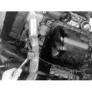
| Fig. 12: Use an extension to help reach the exhaust
pipe bolts
|
- Remove the spare tire from the engine compartment.
- Disengage the emission control system hoses from the air cleaner. Remove
the air cleaner brackets and the wing nut, then lift the air cleaner assembly
off the carburetor.
- Position a drain pan (to catch the gasoline) under the fuel line union.
At the union, remove the hose clamp, then pull the hose(s) to disconnect them.
- Position a drain pan under the engine, remove the drain plug and drain the
oil from the crankcase.
- To drain the engine coolant, perform the following procedures:
- Position a clean container, large enough to hold the contents of the
cooling system, under the radiator drain plug.
- Open the drain plug on the radiator; turn it so that it's slot faces
downward.
- Disconnect both the hoses from the radiator.
- Disconnect the heater hoses from the pipe on the side of the engine.
- If equipped with an automatic transaxle, disconnect the oil cooler lines
from the radiator.
| Fig. 13: Remove the timing hole cover from the
torque converter housing
|
- Disengage the following electrical wiring connectors:
- Alternator multi-connector
- Oil pressure sender connector
- Engine cooling fan connectors
- Temperature sender connector
- Primary distributor lead
- Secondary ignition leads (ignition side)
- Starter wiring harness
- Anti-dieseling solenoid lead
- Automatic choke lead
- EGR vacuum solenoid
- EGR coolant temperature switch
- If equipped with an automatic transaxle, disconnect the neutral safety
switch harness and downshift solenoid harness.
- Loosen the radiator–to–chassis bolts, remove the ground lead
from the upper side of the radiator and the radiator.
NOTE: On 4WD models, remove the engine fan from the pulley.
- To remove the crankshaft damper, perform the following procedures:
- Remove the front nut from the damper.
- Remove the nut on the body bracket and withdraw the damper.
- Pull the damper rearward, away from the engine lifting hook; be careful
not to lose any of the damper parts.
- Remove the starter–to–engine bolts and the starter from the
vehicle.
- Disconnect the following cables, hoses and linkages, by performing the following
procedure:
- Loosen the screw on the carburetor throttle lever. Remove the outer
end of the accelerator cable and withdraw it.
- Remove the vacuum hose and the purge hose from the vapor canister.
- If equipped with a manual transaxle, remove the clutch return spring
from the release lever/intake manifold and the clutch cable from the lever.
- If equipped with an automatic transaxle, disconnect the vacuum hose
from the transaxle.
- Disconnect the vacuum hose from the power brake unit (if equipped).
- On 4WD models, remove the skid plate–to–chassis bolts and the
plate.
| Fig. 14: Using a floor jack, position it under the
transaxle to support its weight when the engine is removed
|
| Fig. 15: Use a chain and hoist to remove the engine
from the vehicle
|
- To remove the Y–shaped exhaust pipe, perform the following procedures:
- Remove the exhaust pipe-to-cylinder head nuts.
- Remove the exhaust pipe–to–pre–muffler nuts/bolts.
- While supporting the exhaust pipe by hand, remove the exhaust pipe–to–transaxle
bracket bolts, then lower the exhaust pipe.
- If equipped with an automatic transaxle, remove the torque converter bolts
by performing the following procedures:
- Remove the timing hole cover from the torque converter housing.
- Through the timing hole, remove the torque converter–to–drive
plate bolts.
WARNING
Be careful that the bolts DO NOT fall into the torque converter housing.
- Connect a chain hoist and a cable to the engine, with hooks at the front
and rear engine hangers. Adjust the hoist so that the weight of the engine
is supported but DO NOT raise the engine.
- Using a floor jack, position it under the transaxle to support it's weight
when the engine is removed.
- Remove the engine–to–transaxle nuts (four each on top and bottom).
- Remove the front engine mount–to–crossmember nuts.
- Using the hoist, raise the engine slightly, about 1 in. (25mm). Keeping
it level, move the engine forward, off the transaxle input shaft.
WARNING
DO NOT raise the engine more than 1 in. (25mm) prior to removing it from
the input shaft or damage may occur to the driveshaft double offset joints.
If equipped with a manual transaxle, be sure that the input shaft does not
interfere with the clutch spring assembly; if equipped with an automatic
transaxle, leave the torque converter on the transaxle input shaft.
- Hoist the engine carefully until it is completely out of the vehicle, then
secure it onto a workstand.
To install:
- When installing the engine, use new gaskets and observe the following torque
specifications:
- Transaxle-to-engine bolts: 34–40 ft. lbs. (46–54 Nm)
- Torque converter bolts: 17–20 ft. lbs. (23–27 Nm)
- Crossmember bolts: 14–24 ft. lbs. (18–32 Nm)
- Crankshaft damper nut: 7–10 ft. lbs. (9–13 Nm)
- Exhaust pipe-to-engine bolt: 19–22 ft. lbs. (25–29 Nm)
- Premuffler nuts: 31–38 ft. lbs. (42–51 Nm)
- Radiator bolts: 6–10 ft. lbs. (8–13 Nm)
- Adjust of the clutch and accelerator linkage. Refill the crankcase and cooling
system.
NOTE: Use care not to damage the input shaft splines or
the clutch spring when lowering the engine in place.
- When installing the crankshaft damper, perform the following adjustments:
- Tighten the body bracket nut.
- Turn the front nut until the clearance between the front washer and
rubber cushion is zero.
- Insert the bushing and tighten the front nut.