NOTE: Use this procedure to remove the entire suspension assembly.
If only shock and/or spring removal are desired, use the procedure given under
Shock Absorbers.
It is desirable that removal and installation of the front suspension be performed
with the car up on a lift or over a pit. If this is not possible, then you will
need a jack and jackstands to raise and support the vehicle.
| Fig. 1: Exploded view of the MacPherson strut front suspension — 1972–74
models
|
| Fig. 2: Exploded view of the MacPherson strut suspension — 1975–79
models
|
| Fig. 3: Exploded view of the MacPherson strut suspension — 1980–84
models
|
- Remove the negative (-) battery cable.
- Remove the hub caps and loosen the lug nuts.
- Raise the vehicle until the tire clears the ground and remove the lug nuts
and the wheel/tire assembly.
- Place the jackstands under the vehicle and remove the jack. Perform this
operation on the other side also if the suspension is to be removed from both
sides of the vehicle.
- Remove the hand brake cable bracket and the handbrake cable hanger from
the transverse link and the tie rod end.
- Remove the hand brake cable end.
- Remove the axle nut, lockplate, washer, and center piece.
- Remove the front brake drums by using a puller.
- Disconnect the brake hoses from the brake fluid pipes. Plug the openings
to prevent fluid loss.
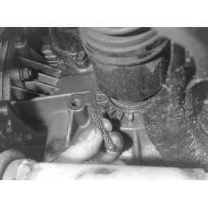
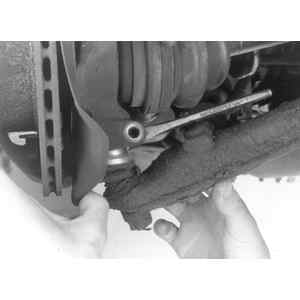
| Fig. 4: Remove the spring pin from the double offset
joint and discard it
|
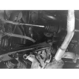
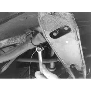
| Fig. 5: Remove the transverse link (lower control
arm) by loosening the locknut nut which holds the transverse link
to the inner pivot shaft of the crossmember
|
- Remove the backing plates with the brake assemblies attached.
- On cars equipped with front disc brakes, remove the hand brake cable end
from the caliper lever.
- Disengage the outer cable clip from the cable end support bracket at the
caliper.
- Disengage the brake line from the caliper and remove it from the bracket.
- Unfasten the hand brake cable bracket from the housing mount by loosening
the nuts.
| Fig. 6: Remove the nuts and ball stud from the knuckle
arm of the tie rod end ball joint housing
|
| Fig. 7: Disconnect the stabilizer by removing the
bolt at the bracket connecting one end of the stabilizer to the leading
rod, and then removing the nuts fixing the bracket to the rear crossmember
|
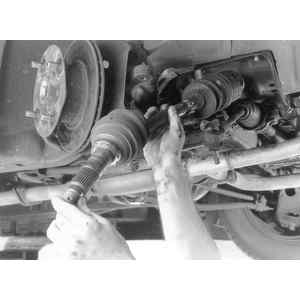
| Fig. 8: Pull the double offset joint out of the driveshaft
and then remove the suspension assembly from the body
|
- Drive out the spring pins of the double offset joint side by using a drift
pin and a hammer. The double offset side of the axle is the side closest to
the transaxle.
- Remove the transverse link (lower control arm) by loosening the locknut
nut which holds the transverse link to the inner pivot shaft of the crossmember.
- Loosen and remove the nuts which clamp the transverse link to the stabilizer.
- Remove the transverse link rearward from the crossmember by using a lever
and pulling the transverse link out from the end of the stabilizer.
- Remove the cotter pin from the castle nut.
- Remove the nuts and ball stud from the knuckle arm of the tie rod end ball
joint housing. Take care not to bend the housing.
- On models from 1975–84, disconnect the leading rod from the rear crossmember
by removing the self-locking-nut, washers, plates, bushings and pipe.
- On models from 1975–84, disconnect the stabilizer by removing the
bolt at the bracket connecting one end of the stabilizer to the leading rod,
and then removing the nuts fixing the bracket to the rear crossmember.
CAUTION
Secure the spring with a spring compressor before loosening the upper strut
nut.
- Remove the nuts which hold the strut mount to the body (suspension assembly
upper mounting nut to the top of the shock absorber tower).
- Pull the double offset joint out of the driveshaft and then remove the suspension
assembly from the body.
- Reverse the above process to install the suspension assembly, and torque
the components to the following specifications:
- Strut-to-body nuts to 22–29 ft. lbs. (29–39 Nm).
- Strut-to-steering knuckle housing bolts to 22–29 ft. lbs. (29–39
Nm).