Previous Next

OVERHAUL

  1. Follow the removal procedure outlined previously.
  2. Remove any sludge and dirt from the outer part of the caliper.
  3. On 1983–84 models, remove the sleeve and then the lock pin boot.

    WARNING
    Do not allow dirt to enter the brake fluid inlet.

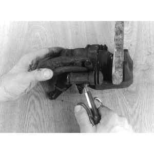
    Fig. 1: Use compressed air to draw out the piston . . .

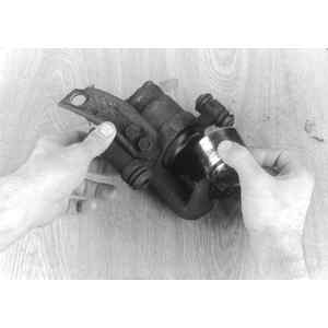
    Fig. 2: . . . then remove the piston from the caliper

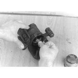
    Fig. 3: Avoid scratching the bore when extracting the piston seal

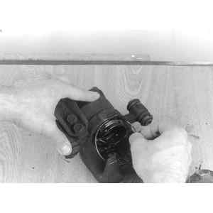
    Fig. 4: Removing the cap ring and lever

  4. Remove the boot ring and piston boot.
  5. 1980–84 models, remove the guide pin boot from the caliper by alternately tapping both dowels on the boot.
  6. Draw out the piston by applying compressed air at the brake fluid inlet. Excessive pressure is not necessary.
  7. Remove the piston seal. Be careful not to scratch the inner wall of the cylinder.
  8. Remove the cap ring and lever cap.
  9. Remove the snapring from the spindle.
  10. Compress the spring washers with a puller to eliminate the force retaining the handbrake lever and spindle, then slide out the lever and spindle.
  11. Remove the connecting link.

    To install:

  12. Clean the inner part of the cylinder with fresh brake fluid and make sure that the inner wall of the brake cylinder is not scratched or corroded.
  13. Apply a thin coat of silicon lubricant to a new piston seal and insert the seal into the groove.
  14. After inspecting the piston for scratches, apply a thin coat of brake fluid to the piston and insert it into the cylinder.

    Fig. 5: Installing the piston seal

    Fig. 6: Carefully insert the piston into the bore

    Fig. 7: Be sure the spring hooks and fits into the groove into the lever and spindle as shown

    Fig. 8: Inserting the spindle

  15. Inspect the piston boot for scratches and replace if necessary.
  16. Apply a thin coating of grease to the rim of the boot and attach it in the cylinder grooves on 1975–79 models.
  17. On 1980–84 models, apply the grease into the grooves in the cylinder and those along the circumference of the piston head.
  18. Attach the boot in the cylinder grooves. Make sure the boot is not twisted anywhere.
  19. Attach the outer boot ring.
  20. Apply a thin coat of silicone lubricant to the spindle assembly O-ring and insert the spindle assembly.

    Fig. 9: Lever, shaft spring and cap as an assembly

    Fig. 10: Installing the snapring

    Fig. 11: Assemble handbrake spindle spring washers as shown

  21. On 1980–84 models, apply the silicone to the section of the spindle where the spring washers go, into the spaces between the spring washers, and onto the caliper body surface where the washers bear.
  22. Apply the same lubricant to the recess in the caliper body where the O-ring fits.
  23. If replacing the spring washers, assemble them in the sequence shown.
  24. Insert the spindle assembly into the cylinder by turning it clockwise from the opening at the bottom of the caliper body.
  25. On 1975–79 models, insert the handbrake lever and spindle shaft assembly at the rear of the caliper. Be careful not to knock the connecting link out of place.
  26. On 1980–84 models, you'll need some sort of tapered mandrel to install the O-ring.
  27. Coat the O-ring with silicone compound and install it into the recess carefully.
  28. Apply a grease designed for this type of service (example: NIGLUBE RX-2) to the head of the spindle assembly and onto the inner wall of the caliper body.
  29. Install the connecting link and return spring.
  30. Now, press in a set of spring washers and hold them there with a puller.
  31. Apply the grease to the grooves in the lever and spindle in which the lever cap and connecting link are to be fitted.
  32. Make sure the caliper bore is clean.
  33. Then, fit the connecting link into the groove at the head of the spindle. Insert the lever and spindle complete with the lever cap and garter spring.
  34. Make sure the inner tip of the return spring hooks and that it fits into the groove in the lever and spindle. Then remove the puller.
  35. Insert the handbrake lever and spindle shaft assembly at the rear of the caliper. Be careful not to knock the connecting link out of place.
  36. Apply silicone grease to the groove of the caliper body where the lever cap will go. Apply it also to the snapring.
  37. Install the snapring at the end of the lever and spindle shaft. Then apply sufficient silicone grease to the space around the connecting link and lever and spindle to fill the inside of the lever cap after it is installed.
  38. Fit the lever cap into the slot at the rear of the caliper body and anchor it in place with the cap ring. Make sure you don't damage the lever cap with the sharp edge of the cap ring.
  39. On late model calipers with guide pins, make sure the hole the guide pin slides into is clean. Install a new guide pin boot by evenly tapping all around the metal periphery.
  40. Make sure to rotate the caliper piston to the proper position.
  41. On 1980–84 calipers, which use guide pins and lock pins, coat the entire guide pin, and all but the outer end of the lockpin, with silicone grease.
  42. Make sure both boots fit properly in the guide pin and lock pin grooves. If the boots get full of air during installation, simply squeeze them gently to release excess air.
  43. Install the calipers.
  44. Bleed the system.

Previous Next