WARNING
Do not hot tank clean any aluminum parts or they will be ruined. Use carburetor
solvent for cleaning.
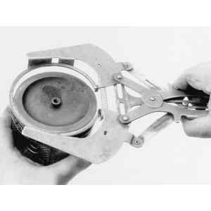
| Fig. 1: Use a ring expander to remove the piston rings
|
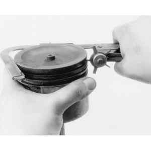
| Fig. 2: Clean the piston using a ring groove cleaner
|
Using a piston ring expanding tool, remove the piston rings from the pistons; any other method (screwdriver blades, pliers, etc.) usually results in the rings being bent, scratched or distorted and/or the piston itself being damaged.
Clean the varnish from the piston skirts and pins with a cleaning solvent. DO NOT WIRE BRUSH ANY PART OF THE PISTON. Clean the ring grooves with a groove cleaner and make sure that the oil ring holes and slots are clean.
Inspect the piston for cracked ring lands, scuffed or damaged skirts, eroded areas at the top of the piston. Replace the pistons that are damaged or show signs of excessive wear. Inspect the piston ring grooves for nicks or burrs that might cause the rings to hang up.
Measure the piston skirt perpendicular to the piston pin axis and note this figure for the piston clearance check. If installing replacement pistons, follow the manufacturers recommendations on where to measure the piston.
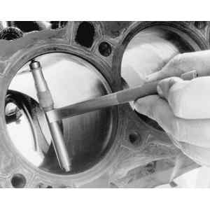
| Fig. 3: A telescoping gauge may be useful to measure
the cylinder bore diameter
|
Using a telescoping gauge or an inside micrometer, measure the diameter of the cylinder bore, perpendicular (90°) to the piston pin, at 1–2 1⁄2 inch (25–64mm) below the surface of the cylinder block. The difference between the two measurements is the piston clearance.
If the clearance is within specifications or slightly below (after the cylinders have been bored or honed), finish honing is all that is necessary, If the clearance is excessive, try to obtain a slightly larger piston to bring the clearance within specifications. If this is not possible, obtain the first oversize piston and hone the cylinder or (if necessary) bore the cylinder to size.
When measuring the cylinder bore, take measurements in several places. If the cylinder bore is tapered or is out-of-round, it is advisable to rebore for the smallest possible oversize piston and rings. After measuring, mark the pistons with a felt-tip pen for reference during assembly.
NOTE: Boring of the cylinder block should be performed by a reputable machine shop with the proper equipment. In some cases, clean-up honing can be done with the cylinder block in the vehicle, but most excessive honing and all cylinder boring MUST BE done with the block stripped and removed from the vehicle.
Wash the connecting rods in cleaning solvent and dry with compressed air. Check for twisted or bent rods and inspect for nicks or cracks. Replace the connecting rods that are damaged.
Install the cap on the rod and tighten to specification. Using an inside micrometer, measure the inside bore diameter perpendicular (90°) to the axis of rod and once again along the axis of the rod. If the two measurements are not within specification, have the rod resized by a competent machine shop.
NOTE: It is normal for the inside diameter of the rod to be slightly larger when measured perpendicular (90°) to the axis of the rod.
| Fig. 4: Checking the bearing journal outside diameter
with a micrometer
|
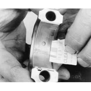
| Fig. 5: After the cap is removed, use the scale supplied
with the gauge to check clearances
|
Measure the bearing journals using a micrometer, to determine diameter, journal taper and eccentricity. If crankshaft journals appear defective, or do not meet tolerances, the crankshaft will require grinding.
Assemble the case halves with the bearings installed and tighten to specification. Using a telescope gauge and micrometer, measure bearing I.D. parallel to piston axis and at 30°on each side of piston axis. Subtract journal O.D. from bearing I.D. to determine oil clearance.
An alternate method is to measure the oil clearance on each crankshaft bearing by means of Plastigage® .
Wipe off oil, dust, etc. on the surfaces to be measured. Install the bearings in the crankcase and set the crankshaft in position. Cut the Plastigage® to the bearing width and place it on the journal parallel with the crankshaft axis. Be careful not to put it on the oil hole or groove. Bring together the crankcase halves and tighten the bolts and nut to the specified torque.
WARNING
During the work, the crankshaft must not be turned, nor the crankcase inverted.
Remove all the bolts and nut and separate the crankcase. Measure the Plastigage® width with the scale printed on the Plastigage® case. If the measurement is not within the specification, replace the defective bearing with an undersize one, and replace or recondition the crankshaft as necessary.