CAUTION
When draining the coolant, keep in mind that cats and dogs are attracted to
ethylene glycol antifreeze, and could drink any that is left in an uncovered
container or in puddles on the ground. This will prove fatal in sufficient quantity.
Always drain the coolant into a sealable container. Coolant should be reused
unless it is contaminated or several years old.
| Fig. 1: Intake and exhaust manifold assembly — 1.2L
carbureted engine
|
| Fig. 2: Intake and exhaust manifold assembly — 1.2L
fuel injected engine
|
- Disconnect the negative battery cable.
- Drain the cooling system into a suitable container.
- Remove the air cleaner assembly.
- Tag and disconnect the upper radiator hose and heater hose from the intake
manifold.
- Disconnect the electrical harnesses and ground straps from the intake manifold.
- Disconnect the accelerator linkage from the carburetor or throttle body
assembly.
- Tag and disconnect all the vacuum lines from the intake manifold, carburetor
or throttle body.
- Remove the air suction manifold pipe.
- Remove the intake manifold mounting bolts.
- Remove the intake manifold assembly.
- Remove all gasket material from both mating surfaces.
- Installation is the reverse of removal. Secure all components accordingly.
- Position the intake manifold on the engine using a new gasket, and loosely
install the intake manifold bolts. With all the bolts installed, tighten them
(starting from the center and moving outward) to 14–22 ft. lbs. (20–29
Nm).
- Attach all hoses to their appropriate locations.
- Refill the cooling system and connect the negative battery cable.
- Start the vehicle and check for any sucking noise indicating a leak.
| Fig. 3: Intake manifold assembly — 1.6L
and 1.8L carburetor engine
|
| Fig. 4: Intake manifold assembly — 1.8L
single port fuel injected engine
|
| Fig. 5: Intake manifold assembly — 1.8L
multi-port fuel injected engine
|
- Relieve the fuel system pressure.
- Disconnect the negative battery cable.
- Disconnect the fuel lines.
- Drain the cooling system into a suitable container. Remove the radiator
hoses.
- On turbocharged models, remove the air duct with the airflow meter attached.
On all other models, remove the air duct.
- On turbocharged models, remove the turbo cooling hose and turbocharger.
- Remove the front exhaust pipe from the cylinder head as required.
- Tag and disconnect the distributor high tension wires, then matchmark and
remove the distributor.
- Label and disconnect all applicable vacuum hoses.
- Remove the alternator, if needed for additional working space.
- Remove the silencers and silencer hoses. Remove the air cleaner assembly.
- Remove the air suction valves and hoses.
- Remove the EGR cover and EGR pipe.
- Remove the PCV valve and blow-by hoses.
- Label and disconnect all applicable electrical harnesses.
- Disconnect the accelerator cable.
- Remove the intake manifold bolts and carefully lift the intake manifold
off the engine.
- Clean all gasket material from the mating surfaces.
- Installation is the reverse of removal. Tighten all components to specifications.
- Use a straightedge feeler gauge to inspect the intake manifold for flatness.
Distortion should not exceed 0.020 inch (0.5mm).
- Install the intake manifold using new gaskets, and secure in place with
the mounting bolts. Tighten the bolts to 13–16 ft. lbs. (18–22
Nm).
- Inspect all electrical connectors for damage and replace as necessary. Attach
all electrical connectors.
- Tighen the EGR cover and pipe bolts to 23–27 ft. lbs. (31–37
Nm).
- Inspect all vacuum lines for damage and replace as necessary.
- On turbocharged models, install the turbo cooling hose and turbocharger
and the air duct with the airflow meter.
- Install the radiator hose and fill the cooling system.
- Connect the negative battery cable, start the engine and allow it to reach
operating temperature. Check for leaks. Test drive the vehicle.
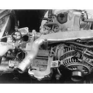
| Fig. 6: Intake manifold assembly — 2.2L
engine
|
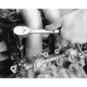
| Fig. 7: Loosen and remove the intake manifold retainer
bolts — 2.2L engine shown
|
| Fig. 8: Carefully lift off the intake manifold assembly
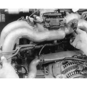
|
| Fig. 9: Remove and discard the intake manifold gaskets
|
- Release the fuel system pressure.
- Disconnect the negative battery cable and remove the engine cover.
- Drain the cooling system into a suitable container.
- Remove the accessory drive belt(s).
- Remove power steering pump and or, alternator for added clearance.
- Label and disconnect all electrical harnesses leading to the intake manifold.
- Label and disconnect all vacuum hoses leading to the intake manifold. Disconnect
the PCV and blow-by hoses.
- Label and disconnect the ignition high tension wires at the spark plugs
and lay them aside.
- Remove the connector bracket attaching bolt.
- Remove the crank angle sensor and cam angle sensor.
- Disconnect the oil pressure switch connector.
- Remove the knock sensor.
- Disconnect the air intake duct.
- On turbocharged models, disconnect the turbo from the intake manifold and
remove.
- Disconnect the fuel supply lines and accelerator linkage.
- Remove the intake manifold bolts and remove the intake manifold and discard
the gaskets.
- Remove the water pipe.
- Clean all gasket material from both mating surfaces.
- Installation is the reverse of removal. Pay particular attention to the
following:
- Use a straightedge and a feeler gauge to inspect the intake manifold
for flatness. Distortion should not exceed 0.020 inch (0.5mm).
- Install the intake manifold and secure in place with retainer bolts.
Tighten the short bolts to 21–25 ft. lbs. (28–34 Nm); the
long bolts to 4–5 ft. lbs. (6–7 Nm).
- Check all vacuum lines for deterioration and replace as necessary. Install
the vacuum lines.
- Check all electrical connectors for damage and replace as necessary. Install
the electrical connectors.
- Install the water pipes and fill the cooling system.
- Start the engine and allow it to reach operating temperature. Check for
leaks and test drive the vehicle.
CAUTION
Fuel injection systems remain under pressure after the engine has been turned
OFF. Properly relieve fuel pressure before disconnecting any fuel lines. Failure
to do so may result in fire or personal injury.
- Disconnect the negative battery cable.
- Drain the cooling system into a suitable container.
- Remove the air intake duct, air cleaner upper cover and the air cleaner
element.
- Properly release the fuel pressure.
- Disconnect the accelerator cable and the cruise control cable, if equipped.
- Disconnect the ground cable from the intake manifold.
- Disconnect the wiring harness from the throttle position sensor, fuel injectors,
idle air control solenoid valve, purge control solenoid valve, and the exhaust
gas recirculation solenoid valve.
- Disconnect the air bypass hose from the idle air control solenoid valve.
- Remove the idle air control solenoid valve from the intake manifold.
- Disconnect the engine coolant hoses from the throttle body.
- Remove the throttle body from the intake manifold and discard the gasket.
- Disconnect the fuel hoses from the fuel pipes.
- Disconnect the EGR and the purge control solenoid valves.
- Disconnect the wiring harness from the knock sensor, camshaft position sensor,
crankshaft position sensor and the oil pressure switch.
- Remove the intake manifold mounting bolts. Remove the manifold and discard
the gaskets.
NOTE: The intake manifold sits on pins that protrude from
the cylinder heads. Be sure the pins remain in the cylinder heads.
- Installation is the reverse of removal. Install the manifold and only use
new gaskets, tighten the mounting bolts to 19 ft. lbs. (26 Nm).
- Connect all wiring and fuel hoses. Be sure to secure the hoses with new
clamps.
- Using new gaskets, install the throttle body to the intake manifold. Tighten
the retaining bolts to 16 ft. lbs. (22 Nm).
- Using a new gasket, install the idle air control solenoid valve to the intake
manifold. Tighten the retaining bolts to 57 inch lbs. (6 Nm).
- Connect the negative battery cable and refill the cooling system. Start
the engine, and bleed the cooling system. Check for leaks.
| Fig. 10: Intake manifold assembly — 2.7L
engine
|
- Relieve the fuel system pressure.
- Disconnect and cap the fuel lines.
- Disconnect the negative battery cable.
- Remove the air duct.
- Tag and remove the ignition wires. remove the distributor from the engine
assembly.
- Remove the alternator.
- Tag and remove all electrical connectors from the intake manifold and throttle
body assembly.
- Tag and remove all vacuum hoses from the intake manifold and throttle body.
- Remove the EGR cover and pipe.
- Disconnect the accelerator linkage.
- Remove the intake manifold mounting bolts, then remove the intake manifold
and gaskets.
To install:
- Clean the gasket mating surfaces thoroughly.
- Using a straightedge and a feeler gauge, inspect the intake manifold for
flatness. Distortion should not exceed 0.020 inch (0.5mm).
- Install the intake manifold using new gaskets and tighten the mounting bolts
to 15 ft. lbs. (20 Nm)S
- The remainder of installation is the reverse of removal.
- Start the engine and allow it to reach operating temperature. Check for
leaks and test drive the vehicle.
| Fig. 11: Intake manifold assembly — 3.3L
engine
|
CAUTION
Fuel injection systems remain under pressure after the engine has been turned
OFF. Properly relieve fuel pressure before disconnecting any fuel lines. Failure
to do so may result in fire or personal injury.
- Relieve the fuel system pressure.
- Disconnect the negative battery cable.
- Remove the collector cover.
- Disconnect the accelerator cable and cruise control cable from the throttle
lever, if equipped.
- Remove the air intake ducts.
- Disconnect the electrical harnesses from the intake manifold sensors and
brackets.
- Detach the electrical connector from the auxiliary air control valve.
- Disconnect and cap the two coolant hoses from the underside of the throttle
body.
- Disconnect the auxiliary air control valve hose from the throttle body.
- Disconnect the PCV hose. Remove the blow-by hose from the cylinder head
cover.
- Disconnect the EGR control hoses from the intake manifold. Remove the EGR
pipe and cover.
- Disconnect the power steering pump electrical harness.
- Disconnect the power brake booster vacuum hose.
- Disconnect and cap the fuel lines from the fuel pipes.
- Remove the drive belt cover and drive belts.
- Unfasten the electrical connections from the alternator.
- Remove the alternator. Refer to Section 2 for removal and installation steps.
- Remove the A/C compressor mounting bolts and position the A/C compressor
aside with the refrigerant lines attached.
- Remove the intake manifold.
- Clean all gasket material from both mating surfaces.
- Installation is the reverse of removal. Tighten all components to specification
and pay particular attention to the following:
- Using new gaskets, tighten the intake manifold bolts to 18 ft. lbs. (24
Nm).
- Install the drive belts and tension as necessary. Install the drive belt
cover.
- Connect the fuel lines to the fuel pipes and attach all vacuum lines.
- Pressurize the fuel system and check for leaks.