Previous Next

Control Arm

REMOVAL & INSTALLATION

Justy

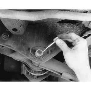
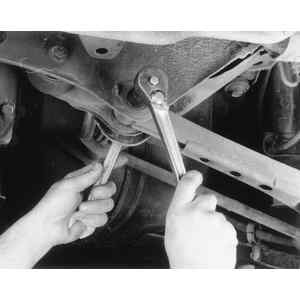
Fig. 1: Loosening the control arm-to-frame retainer nut and bolt — Justy

  1. Disconnect the negative battery cable.
  2. Raise and safely support the vehicle on jackstands.
  3. Remove the tire and wheel assembly.
  4. Remove the trim cover over the upper strut mount.
  5. Support the control arm with a suitable jack, and remove the long bolt that connects the knuckle to the outboard control arm.
  6. Slowly lower the control arm to remove the coil spring.
  7. Remove the inner control arm to frame nut and bolts, then remove the lower control arm.
  8. Installation is the reverse of removal. Secure all components to specifications. Refer to the chart at the end of this section.
  9. Check the front end alignment and adjust as necessary.
Sedan, Coupe, Loyale, XT, Wagon and Brat

Fig. 2: Rear control arm assembly — Sedan, Coupe, Loyale, XT, Wagon and Brat

OUTER CONTROL ARM
  1. Raise and safely support the vehicle on jackstands.
  2. Remove the tire and wheel assembly.
  3. Support the control arm assembly with a suitable jack.
  4. Remove the three bolts securing the inner and outer control arms together.
  5. Remove the nut and bolt securing the outer control arm to the suspension assembly.
  6. Remove the outer control arm.
  7. Installation is the reverse of removal. Tighten all components to specifications, refer to the chart at the end of this section.
  8. Check and adjust the rear alignment.
INNER CONTROL ARM
  1. Raise and safely support the vehicle on jackstands.
  2. Remove the tire and wheel assembly.
  3. Support the control arm assembly.
  4. Remove the three bolts securing the inner and outer control arms together.
  5. On 4WD vehicles perform the following steps.
    1. Remove the spring pin securing the halfshaft to the carrier assembly.
    2. Remove the cotter pin and castle nut from the rear halfshaft.
    3. Remove the muffler and tail pipe assembly, if the right side is being serviced.
    4. Disconnect the halfshaft from the differential carrier.
    5. Using a suitable halfshaft removal tool, unseat the halfshaft from the hub and remove the halfshaft from the vehicle.
  6. Remove the shock absorber assembly.
  7. Cap and disconnect the brake hose at the rear suspension member.
  8. Remove the inner control arm-to-frame mounting nut and bolt, and remove the control assembly.
  9. With the assembly removed from the vehicle remove all necessary brake components.
  10. Installation is the reverse of removal.
  11. Bleed the brake system. Check and adjust the rear alignment.
Legacy and Impreza
FRONT WHEEL DRIVE

Fig. 3: Front wheel drive rear crossmember and link assembly — Legacy and Impreza

Fig. 4: Matchmark the inside retainer/adjuster bolt . . .

Fig. 5: . . . then loosen and remove the retainer/adjuster nut and bolt

  1. Raise and support the vehicle safely on jackstands.
  2. Remove the rear exhaust pipe and muffler.
  3. Remove the stabilizer bar from the rear lateral link.
  4. Matchmark the adjusting bolt to the crossmember.
  5. Remove the bolts securing the lateral links to the crossmember.
  6. Turn the lateral link cap counterclockwise until it contacts the stopper, then remove the cap.
  7. Secure the lateral link adjusting bolt and loosen the self-locking nut.
  8. If removing the right lateral links, remove the bolts securing the crossmember to the body.
  9. Remove the adjustment bolt and links.
  10. Installation is the reverse of removal. Secure the crossmember-to-body the new nuts to 83 ft. lbs. (113 Nm). Tighten the lateral links-to-housing long bolt to 83 ft. lbs. (113 Nm) and short bolt to 33 ft. lbs. (44 Nm).
  11. Check the rear wheel alignment.
ALL WHEEL DRIVE

Fig. 6: All wheel drive rear crossmember and link assembly — Legacy and Impreza

  1. Raise and support the vehicle safely on jackstands.
  2. Remove the wheel.
  3. Remove the stabilizers.
  4. If equipped with ABS, disconnect the sensor harness from the trailing link.
  5. Remove the bolt securing the trailing link to the housing.
  6. Disconnect the inner CV-joint from the differential.
  7. Matchmark the trailing link adjustment bolt to the crossmember.
  8. Remove the outer lateral link on the housing side.
  9. Secure the adjustment bolt and remove the nut.
  10. Remove the bolts securing the lateral links to the crossmember and remove the links.
  11. Installation is the reverse of removal. Tighten the lateral link nuts to 72 ft. lbs. (98 Nm). Tighten the outer lateral link bolt on the housing side new nut to 101 ft. lbs. (137 Nm).
  12. Check the wheel alignment.
SVX
TRAILING LINK

Fig. 7: Rear and trailing link assembly — SVX

Fig. 8: Remove the ABS sensor bracket from the trailing link

Fig. 9: Remove the trailing link retainer nut and bolt

  1. Raise and safely support the vehicle on jackstands.
  2. Remove the tire and wheel assembly.
  3. Disconnect the ABS sensor bracket and parking brake cable bracket from the trailing link.
  4. Remove the cap from the front trailing link bushing.
  5. Remove the front and rear through-bolts and nuts and remove the trailing link.

    To install:

  6. Install the trailing link and install the through-bolts and nuts. DO NOT tighten the nuts and bolts at this time. Install all remaining components at this time and tighten the front trailing link through-bolt to 115 ft. lbs. (157 Nm) and install the cap. Then tighten the rear trailing link through-bolt to 90 ft. lbs. (123 Nm).
LATERAL LINK

Fig. 10: Removing the sway bar link

Fig. 11: Rear and lateral link assembly — SVX

Fig. 12: Lateral link adjuster bolt

  1. Raise and safely support the vehicle on jackstands.
  2. Remove the tire and wheel assembly.
  3. Remove the rear exhaust pipe.
  4. Remove the rear sway bar link.
  5. Remove the ABS sensor bracket and parking brake cable bracket from the trailing link.
  6. Remove the bolt securing the parking brake cable bracket from the floor.
  7. Disconnect the trailing link from the knuckle.
  8. Remove the lateral link-to-knuckle through-bolt and nut.
  9. Separate the inboard CV-joint from the differential carrier.
  10. Matchmark the alignment bolt on the lateral link for installation purposes.
  11. Remove the mounting bolt and remove the lateral link.
  12. Installation is the reverse of removal.
  13. Check the front end alignment and adjust as necessary.

Previous Next