Previous Next

Tie Rod Ends

REMOVAL & INSTALLATION

Except Legacy, Impreza and SVX
  1. Disconnect the negative battery cable.
  2. Raise and safely support the vehicle on jackstands.
  3. Remove the tire and wheel assembly.
  4. Loosen the jam nut 1/4 of a turn.

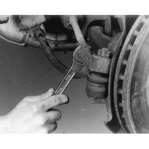
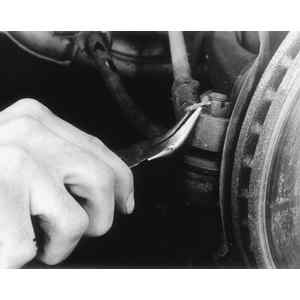
    Fig. 1: Loosening the tie rod locknut

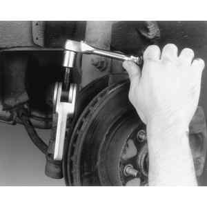
    Fig. 2: Using a tie rod tool to separate the end from the steering knuckle

  5. Remove the cotter pin and castle nut from the outer tie rod end.
  6. Using a suitable tool, separate the tie rod end from the steering knuckle.
  7. Unthread the tie rod end from the rack and pinion assembly.

    To install:

  8. Thread the tie rod end onto the rack and pinion assembly until it is up against the jam nut.
  9. Install the tie rod stud through the steering knuckle and install the castle nut. Tighten the castle nut to 20 ft. lbs. (27 Nm) on all models except SVX, on the SVX tighten to 29 ft. lbs. (39 Nm).
  10. Tighten the jam nut to specifications. Install a new cotter pin.
  11. Install the tire and wheel assembly, lower the vehicle.
  12. Connect the negative battery cable then check the front end alignment and adjust as necessary.

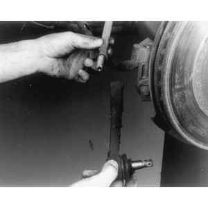
    Fig. 3: Tie rod connected to the steering knuckle assembly — Sedan, Coupe, Loyale, XT, Wagon and Brat

Legacy and Impreza
OUTER

Fig. 4: Loosen the tie rod locknut — Legacy

Fig. 5: Remove the cotter pin from the castle nut

Fig. 6: Using a tie rod tool to separate the tie rod from the steering knuckle

Fig. 7: While counting the turns, remove the tie rod end

  1. Raise the front of the vehicle and support it on jackstands. Remove the wheel.
  2. Remove the cotter pin and the tie rod ball joint stud nut. Note the position of the steering linkage.
  3. Using a suitable ball joint separator tool, remove the tie rod ball joint from the steering knuckle.
  4. Loosen the locknut and remove the tie rod end from the tie rod. Count the number of complete turns it takes to completely remove it.

    To install:

  5. Install the new tie rod end, turning it in exactly as many turns as it was to remove the old one. Make sure it is correctly positioned in relationship to the steering linkage.
  6. Connect the outer tie rod end-to-steering knuckle and install the castle nut. Tighten the nut to 18–22 ft. lbs. (25–29 Nm.).

    NOTE: If the cotter pin holes do not line up never loosen the nut to install the pin. The nut can be tightened up to 60 degrees additional rotation to line up the cotter pin holes.

  7. Install a new cotter pin to the castle nut. Tighten the tie rod end locking nut to 58–65 ft. lbs. (78–88 Nm).
  8. Install the wheel and tire assembly. Lower the vehicle and perform a front end alignment.
INNER
  1. Raise the front of the vehicle and support it on jackstands. Remove the wheel.
  2. Remove the cotter pin and the tie rod ball joint stud nut. Note the position of the steering linkage.
  3. Using a suitable ball joint separator tool, remove the tie rod ball joint from the steering knuckle.
  4. Loosen the locknut and remove the tie rod end from the tie rod. Count the number of complete turns it takes to completely remove it.
  5. Remove the tie rod-to-steering gear locknut.
  6. Remove the clamps that secure the flexible boot to the steering gear.
  7. Slide the boot from the inner tie rod and remove the boot.
  8. Bend the lock plate tabs from the inner tie rod end nut.
  9. Loosen the inner tie rod end nut from the steering gear and remove the inner tie rod end.

    To install:

  10. Using a new lock plate, install the inner tie rod end and tighten the tie rod to 51–65 ft. lbs. (69–88 Nm).
  11. Bend the tabs of the new lock plate to secure the inner tie rod end. Slide the boot onto the steering gear and secure it with new clamps.
  12. Install the outer tie rod-to-steering gear and end, then the locknut turning it in exactly as many turns as it was to remove the old one. Make sure it is correctly positioned in relationship to the steering linkage.
  13. Connect the outer tie rod end-to-steering knuckle and install the castle nut. Tighten the nut to 18–22 ft. lbs. (25–29 Nm.).

    NOTE: If the cotter pin holes do not line up never loosen the nut to install the pin. The nut can be tightened up to 60 degrees additional rotation to line up the cotter pin holes.

  14. Install a new cotter pin to the castle nut. Tighten the tie rod end locking nut to 58–65 ft. lbs. (78–88 Nm).
  15. Install the wheel and tire assembly. Lower the vehicle and perform a front end alignment.

Previous Next