Electronic Control System Component Location
Precautions: General safety (00)
NOTE:
This figure shows component locations for LHD. For RHD, alphabets / numbers with (*) are installed on the opposite side.
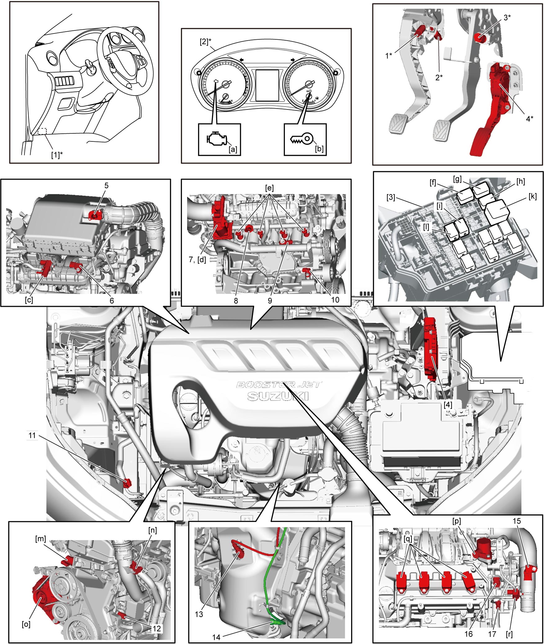
| Information sensors | Control devices | Others | |||
|---|---|---|---|---|---|
| 1. | CPP No.2 switch (M/T model) | [a]: | MIL | [1]: | DLC |
| 2. | CPP No.1 switch (M/T model) | [b]: | Immobilizer indicator light | [2]: | Combination meter |
| 3. | Brake light switch / brake switch | [c]: | EVAP canister purge valve | [3]: | Individual circuit fuse box No.1 |
| 4. | Accelerator pedal assembly (incorporating APP sensor) | [d]: | Electric throttle body assembly | [4]: | ECM |
| 5. | MAF sensor with IAT sensor-1 | [e]: | Fuel injector | ||
| 6. | MAP sensor | [f]: | Radiator cooling fan relay No.1 | ||
| 7. | TP sensor | [g]: | Radiator cooling fan relay No.3 | ||
| 8. | Fuel pressure sensor | [h]: | Radiator cooling fan relay No.2 | ||
| 9. | Knock sensor | [i]: | Fuel pump relay | ||
| 10. | CKP sensor | [k]: | Main relay | ||
| 11. | A/C refrigerant pressure sensor | [l]: | A/C compressor relay | ||
| 12. | Oil temperature sensor | [m]: | OCV | ||
| 13. | HO2S-1 | [n]: | ABV-VSV | ||
| 14. | HO2S-2 | [o]: | Generator | ||
| 15. | Boost pressure sensor with IAT sensor-2 | [p]: | High pressure fuel pump | ||
| 16. | CMP sensor | [q]: | Ignition coil assembly | ||
| 17. | ECT sensor | [r]: | WGV-VSV | ||