Electronic Control System Circuit Diagram
Precautions: General safety (00)
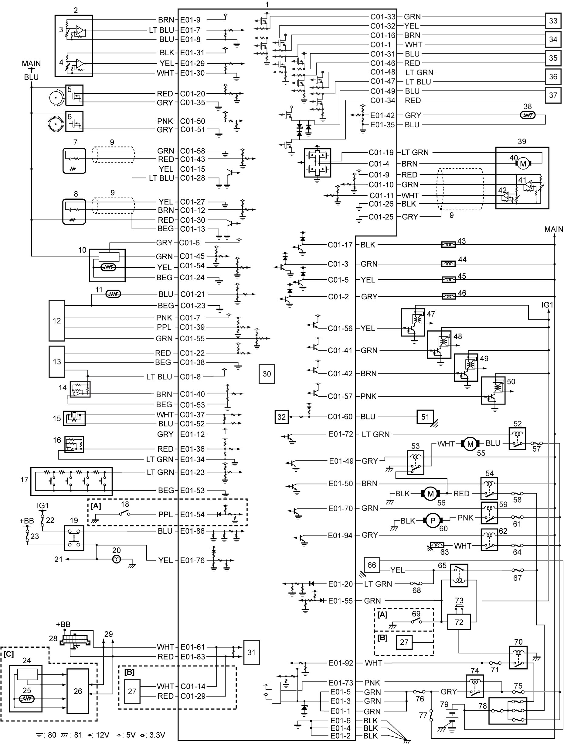
| [A]: | M/T model | 26. | ENG A-STOP control module | 54. | Radiator cooling fan relay No.3 |
| [B]: | A/T model | 27. | TCM | 55. | Radiator cooling fan motor |
| [C]: | ENG A-STOP model | 28. | DLC | 56. | Radiator cooling sub fan motor |
| 1. | ECM | 29. | To other control modules and sensor connected by CAN | 57. | “RDTR” fuse |
| 2. | APP sensor | 30. | Barometric pressure sensor | 58. | “RDTR2” fuse |
| 3. | APP sensor (main) | 31. | CAN driver | 59. | Fuel pump relay |
| 4. | APP sensor (sub) | 32. | LIN driver | 60. | Fuel pump |
| 5. | CMP sensor | 33. | Fuel injector No.1 | 61. | “F/P” fuse |
| 6. | CKP sensor | 34. | Fuel injector No.2 | 62. | A/C compressor relay |
| 7. | HO2S-1 | 35. | Fuel injector No.3 | 63. | A/C compressor |
| 8. | HO2S-2 | 36. | Fuel injector No.4 | 64. | “CPRSR” fuse |
| 9. | Shield wire | 37. | High pressure fuel pump | 65. | Starting motor control relay |
| 10. | MAF sensor with IAT sensor-1 | 38. | Oil temperature sensor | 66. | Starting motor |
| 11. | ECT sensor | 39. | Electric throttle body assembly | 67. | “ST” fuse |
| 12. | Boost pressure sensor with IAT sensor-2 | 40. | Throttle actuator | 68. | “ST SIG” fuse |
| 13. | Fuel pressure sensor | 41. | TP sensor (main) | 69. | CPP No.1 switch |
| 14. | MAP sensor | 42. | TP sensor (sub) | 70. | IG1 relay |
| 15. | Knock sensor | 43. | EVAP canister purge valve | 71. | “IG COIL” fuse |
| 16. | A/C refrigerant pressure sensor | 44. | OCV | 72. | Keyless start control module |
| 17. | Cruise control switch | 45. | ABV-VSV | 73. | Engine switch |
| 18. | CPP No.2 switch | 46. | WGV-VSV | 74. | Main relay |
| 19. | Brake light switch / brake switch | 47. | Ignition coil assembly No.1 | 75. | “FI MAIN” fuse |
| 20. | Brake light | 48. | Ignition coil assembly No.2 | 76. | “INJ DRV” fuse |
| 21. | To other control modules | 49. | Ignition coil assembly No.3 | 77. | “FI” fuse |
| 22. | “CRUISE” fuse | 50. | Ignition coil assembly No.4 | 78. | Main fuse box |
| 23. | “STOP” fuse | 51. | Generator | 79. | Battery |
| 24. | Electric load current sensor | 52. | Radiator cooling fan relay No.1 | 80. | Engine ground |
| 25. | Battery temperature sensor | 53. | Radiator cooling fan relay No.2 | 81. | Body ground |
Terminal Arrangement of ECM Connector
NOTE:
For circuit names and terminal voltages, refer to Inspection of ECM and Its Circuits:K14C.
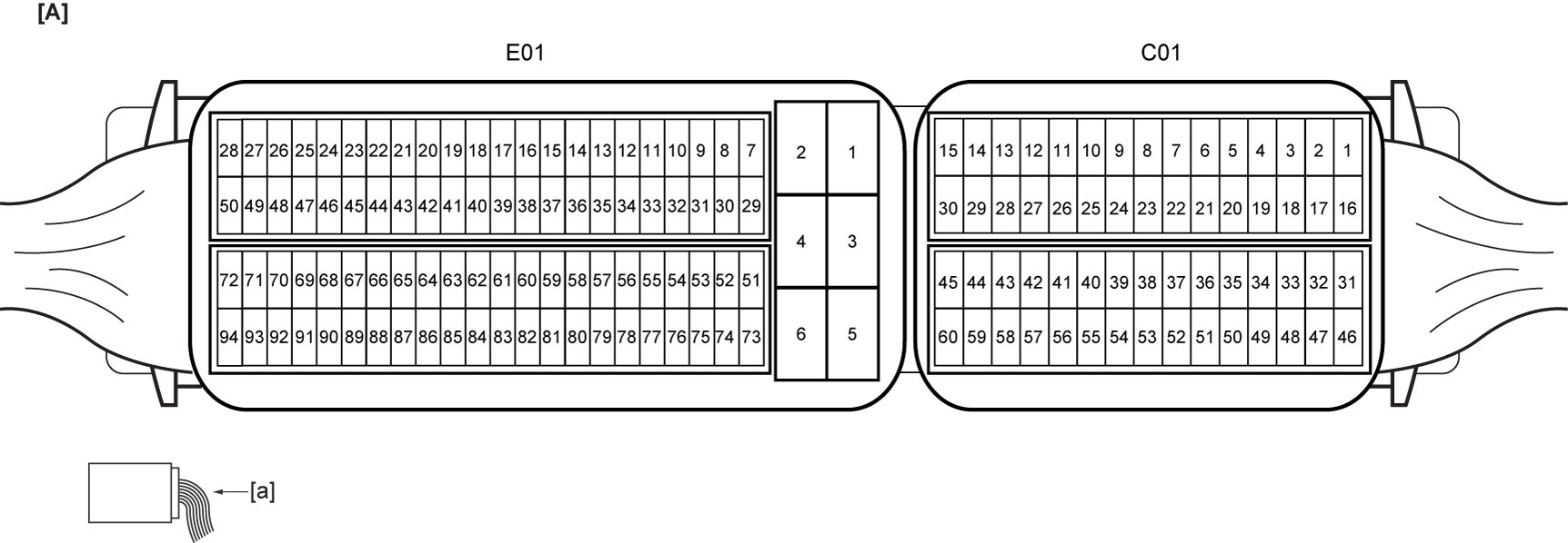
| [A]: | ECM connector (View: [a]) |